- 您現(xiàn)在的位置:買賣IC網(wǎng) > PDF目錄97997 > LB8108M DISK DRIVE MOTOR CONTROLLER, 0.8 A, PQFP44 PDF資料下載
參數(shù)資料
| 型號(hào): | LB8108M |
| 元件分類: | 運(yùn)動(dòng)控制電子 |
| 英文描述: | DISK DRIVE MOTOR CONTROLLER, 0.8 A, PQFP44 |
| 封裝: | QFP-44 |
| 文件頁數(shù): | 5/12頁 |
| 文件大?。?/td> | 199K |
| 代理商: | LB8108M |

Specifications
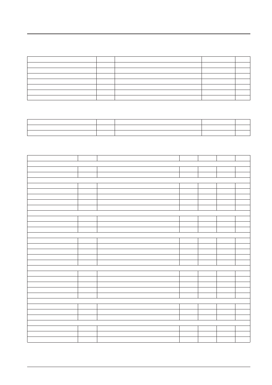
Absolute Maximum Ratings at Ta = 25°C
Allowable Operating Ranges at Ta = 25°C
Electrical Characteristics at Ta = 25°C, VCC = 3 V
No. 4946-2/12
LB8108M
Parameter
Symbol
Conditions
Ratings
Unit
Maximum supply voltage
VCC max
7
V
External input voltage
VEXT max
9
V
H bridge output current
IOUT max
Taking 400 mA per channel as the maximum.
800
mA
Step-up circuit output current
ICD max
150
mA
Allowable power dissipation
Pd max
Independent IC
900
mW
Operating temperature
Topg
–20 to +75
°C
Storage temperature
Tstg
–55 to +150
°C
Parameter
Symbol
Conditions
Ratings
Unit
Supply voltage
VCC
1.6 to 3.5
V
External input voltage
VEXT
5.0 to 8.0
V
Parameter
Symbol
Conditions
min
typ
max
Unit
[Power Supply Block]
Standby current drain
ICCO
S/S = high
100
A
Quiescent current
ICC
S/S = low, with no drive input
16
25
mA
[Step-up Circuit (3.9 V)]
Step-up output voltage
VCD
3.7
3.9
4.1
V
NPN drive current
ID CD
3.0
mA
Load regulation
RLD CD
1000
mV/A
Line regulation
RLN CD
100
mV/V
Minimum off duty
DMIN CD
50
%
[Externally Set Step-Up Circuit]
NPN drive current
ID UP
3.0
mA
Input bias current
IB UP
200
nA
Minimum off duty
DMIN UP
50
%
[H Bridge Output Block, PWM Block]
Output saturation voltage
VH sat
IO = 200 mA, TOP + BOTTOM
0.30
0.45
V
Maximum output voltage
VPWM max
2.25
V
PNP drive current
ID PWM
VOUT/600
mA
Load regulation
RLD PWM
1000
mV/A
Line regulation
RLN PWM
100
mV/V
[Drive Control Block]
Input bias current
IB IN
2.0
A
ASP reference input voltage range
VASPR
1.2
VCD – 1.3
V
Transfer gain
GIN
For RL = 10
7.95
dB
Transfer gain difference (+/-)
G
IN
For RL = 10
–1.0
0
+1.0
dB
Input dead zone voltage
VDZ
–30
0
+30
mV
[Sled Drive Circuit]
SLREF input voltage range
VSLREF
VCD – 0.5
V
Input bias current
IB SLED
200
nA
SLM on voltage
VSLM
2.0
V
[Oscillator Block]
Oscillator power output voltage
VOSCP
VCC – 0.15
V
Oscillator maximum frequency
FMAX
100
kHz
OSC pin input bias current
IB OSC
–2.0
A
Continued on next page.
相關(guān)PDF資料 |
PDF描述 |
|---|---|
| LB8502M | BRUSH DC MOTOR CONTROLLER, 0.003 A, PDSO10 |
| LB8653T | STEPPER MOTOR CONTROLLER, 0.8 A, PDSO24 |
| LB8658FN | STEPPER MOTOR CONTROLLER, 0.8 A, QCC44 |
| LB8658PL | STEPPER MOTOR CONTROLLER, 0.8 A, QCC40 |
| LC7185-8750 | PLL FREQUENCY SYNTHESIZER, 30 MHz, PDIP30 |
相關(guān)代理商/技術(shù)參數(shù) |
參數(shù)描述 |
|---|---|
| LB8109M | 制造商:SANYO 制造商全稱:Sanyo Semicon Device 功能描述:Actuator Driver for Portable CD Players |
| LB8110 | 制造商:PEPPERL+FUCHS 功能描述:LB ComUnit Modular FF Remote I/O, 202431 |
| LB8110M | 制造商:未知廠家 制造商全稱:未知廠家 功能描述: |
| LB8111 | 制造商:SANYO 制造商全稱:Sanyo Semicon Device 功能描述:8mm VTR Sensor Amplifier |
| LB8111V | 制造商:SANYO 制造商全稱:Sanyo Semicon Device 功能描述:8mm VTR Sensor Amplifier |
發(fā)布緊急采購(gòu),3分鐘左右您將得到回復(fù)。