- 您現(xiàn)在的位置:買賣IC網(wǎng) > PDF目錄97997 > LB8108M DISK DRIVE MOTOR CONTROLLER, 0.8 A, PQFP44 PDF資料下載
參數(shù)資料
| 型號: | LB8108M |
| 元件分類: | 運動控制電子 |
| 英文描述: | DISK DRIVE MOTOR CONTROLLER, 0.8 A, PQFP44 |
| 封裝: | QFP-44 |
| 文件頁數(shù): | 3/12頁 |
| 文件大小: | 199K |
| 代理商: | LB8108M |

No. 4946-11/12
LB8108M
First, when VCC is adequately high (about 2.5 V or over) the laser diode is driven by the system consisting of VCC, an
inductor and a Schottky diode without driving LDUPB. Then, when VCC falls and VLD – VLDO become under about 0.3
V, LDUPB is driven, VLD is stepped up, and the circuit is controlled so that VLD – VLDO is held at 0.3 V (typical).
The following describes the laser diode intensity adjustment function supported by the LB8108M.
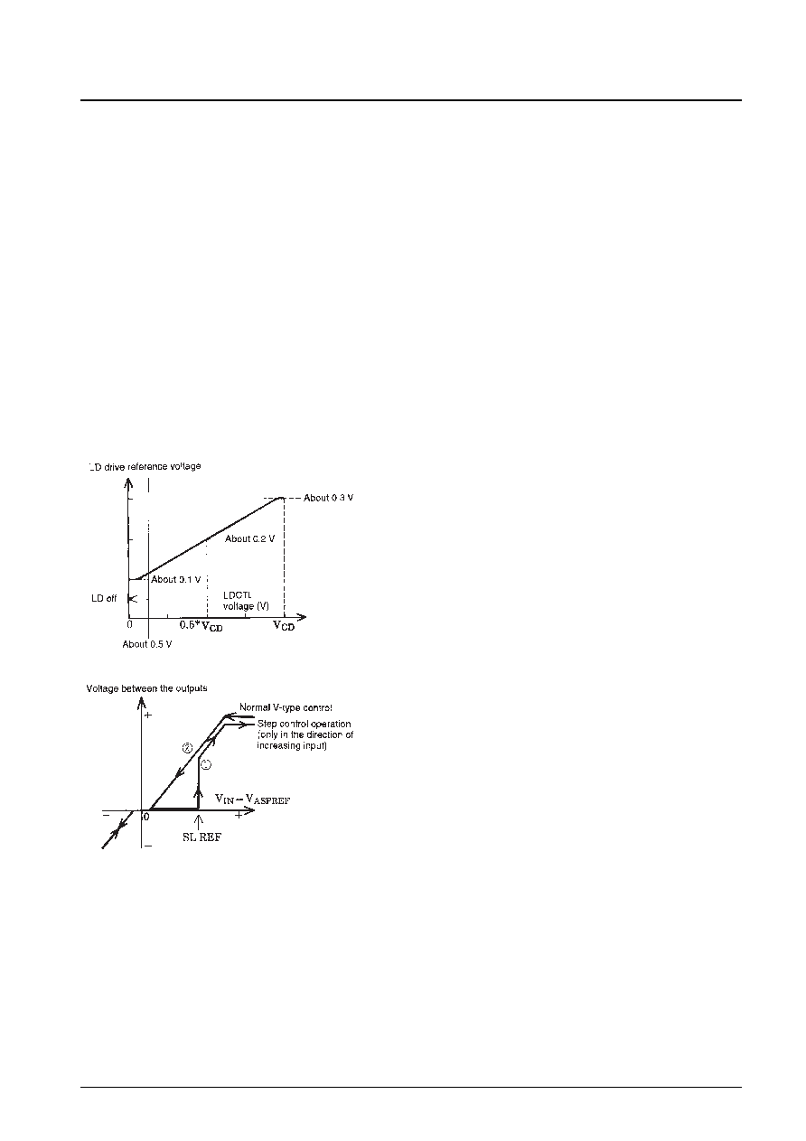
First, set up the pickup so that the monitor diode output is about 0.2 V in the normal usage range.
When LDCTL is in the range 0.0 to 0.5 V the LD drive function will be in the cutoff state and the laser diode will not be
driven. As the LDCTL voltage rises, the LD drive reference voltage shown in the figure varies between 0.1 and 0.3 V.
Then, the VLDO pin voltage is controlled so that the monitor diode output and that reference voltage become identical.
However, since the output current peak is 100 mA (typical), the output voltage will not increase when an output current
in excess of that value is required.
(Since the intensity adjustment will go to its maximum setting when the LDCTL pin is open, an appropriate voltage must
be applied to the LDCTL pin.)
Sled Control
The figure below shows the operation of the LB8108M’s sled actuator step control.
When the SLM pin is set high, the LB8108M operates in the normal V-type control mode. However, the LB8108M can
be set to operate in a sled drive mode that is highly efficient at
reducing power dissipation by setting the SLM pin low.
The step drive start level is input from the SLREF pin. (Only a
voltage higher than VASPREF will be accepted.)
The circuit operates once in step drive mode following the locus
of line
in the figure. Then, on returning, it operates in V-type
control following the locus of line
.
Next, the circuit can be operated in step mode by putting the
input (VIN4) into the reverse region.
(If the input does not enter the reverse region, the circuit will
continue to operate in V-type mode.)
相關(guān)PDF資料 |
PDF描述 |
|---|---|
| LB8502M | BRUSH DC MOTOR CONTROLLER, 0.003 A, PDSO10 |
| LB8653T | STEPPER MOTOR CONTROLLER, 0.8 A, PDSO24 |
| LB8658FN | STEPPER MOTOR CONTROLLER, 0.8 A, QCC44 |
| LB8658PL | STEPPER MOTOR CONTROLLER, 0.8 A, QCC40 |
| LC7185-8750 | PLL FREQUENCY SYNTHESIZER, 30 MHz, PDIP30 |
相關(guān)代理商/技術(shù)參數(shù) |
參數(shù)描述 |
|---|---|
| LB8109M | 制造商:SANYO 制造商全稱:Sanyo Semicon Device 功能描述:Actuator Driver for Portable CD Players |
| LB8110 | 制造商:PEPPERL+FUCHS 功能描述:LB ComUnit Modular FF Remote I/O, 202431 |
| LB8110M | 制造商:未知廠家 制造商全稱:未知廠家 功能描述: |
| LB8111 | 制造商:SANYO 制造商全稱:Sanyo Semicon Device 功能描述:8mm VTR Sensor Amplifier |
| LB8111V | 制造商:SANYO 制造商全稱:Sanyo Semicon Device 功能描述:8mm VTR Sensor Amplifier |
發(fā)布緊急采購,3分鐘左右您將得到回復。