- 您現(xiàn)在的位置:買賣IC網(wǎng) > PDF目錄67755 > LA79500E (SANYO SEMICONDUCTOR CO LTD) 6-CHANNEL, VIDEO MULTIPLEXER, QFP80 PDF資料下載
參數(shù)資料
| 型號(hào): | LA79500E |
| 廠商: | SANYO SEMICONDUCTOR CO LTD |
| 元件分類: | 多路復(fù)用及模擬開關(guān) |
| 英文描述: | 6-CHANNEL, VIDEO MULTIPLEXER, QFP80 |
| 封裝: | 14 X 20 MM, QIP-80 |
| 文件頁數(shù): | 4/16頁 |
| 文件大?。?/td> | 653K |
| 代理商: | LA79500E |
LA79500E
No.A0259-12/16
1) Data transfer manual : [1] is High level. [0] is Low level.
I
2C-BUS control system is adopted in SW LSI and SW LSI is controlled by SCL (Serial Clock) and SDA (Serial
Data). At first, please set up the START condition*1 by these two terminals (SCL and SDA). And next, please input
the 8bits data which should be synchronized with SCL into SDA terminal Still more, please give priority to high
rank bit at data transfer order (MSB
→LSB). The 9th bit is called as ACK (Acknowledge), SW LSI sends [0] to the
SDA terminal during SCL [1] period. So, please open the port of micro-processor during this period. And next,
please transfer sub-address data (called as Group) and control data. As thus the Data transfer Stop condition*2 is
finished.
*1 : SDA rise up during SCI is [1]
*2 : SDA fall down during SCL is [1]
2) Transfer data format
The transfer data is composed by START condition , Slave address data, sub-address data, control data and STOP
condition.
There are 6 control groups.
After setting up the START condition, please transfer the Slave Address. sub-address data and next control data
(Please see the Fig.1)
Slave Address is composed by 7bits, and this bit 8th bit should be set as [0] at write mode and [1] at read mode.
This 8th bit called as R/W bit, and this bit shows the data transmission direction. [0] means send mode (accept mode
with SW LSI) and [1] means accept mode (send mode with SW LSI) fundamentally.
The both of sub-address data and control data are composed by 8bits, and the one control action is defined with
combination of these two data. And if you want to control 2 or more groups at the same mode, you can realize it by
sending some control data together.
The data makes meaning with all bits, so you cannot stop the sending until all data transfer is over. If you want to
stop transfer action, please transfer the STOP condition.
You can select how to send as follws.(write mode)
Pattern A Start condition + Slave Address + Sub Address 00 + Data 00 + Data 01 + Data 02 + Data 03 +
Data 04 + Data 05 + Stop condition
Pattern B Start condition + Slave Address + Sub Address 01 + Data 01 + Data 02 + Data 03 + Data 04 +
Data 05 + Stop condition
Pattern C Start condition + Slave Address + Sub Address 02 + Data 02 + Data 03 + Data 04 + Data 05 +
Stop condition
Pattern D Start condition + Slave Address + Sub Address 03 + Data 03 + Data 04 + Data 05 + Stop condition
Pattern E Start condition + Slave Address + Sub Address 04 + Data 04 + Data 05 + Stop condition
Pattern F Start condition + Slave Address + Sub Address (01 or 02 or 03 or 04 or 05) +
Data (01 or 02 or 03 or 04 or 05) + Stop condition (send only 1Data)
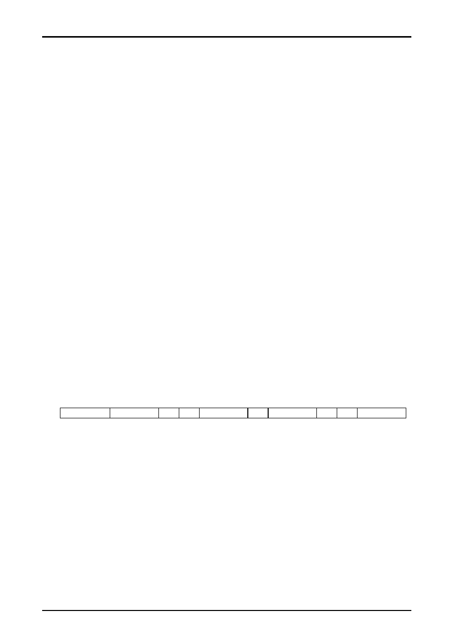
START condition
Slave Address
R/W
ACK
Sub-Address
ACK
Control data
ACK
...
STOP condition
Fig.1 Data Structure
相關(guān)PDF資料 |
PDF描述 |
|---|---|
| LB11610P | BRUSHLESS DC MOTOR CONTROLLER, 1.5 A, PDSO36 |
| LB11620GP | BRUSHLESS DC MOTOR CONTROLLER, 0.03 A, QCC24 |
| LB11620GP | BRUSHLESS DC MOTOR CONTROLLER, 0.03 A, QCC24 |
| LB11681H | BRUSHLESS DC MOTOR CONTROLLER, 1.3 A, PDSO28 |
| LB11693H | BRUSHLESS DC MOTOR CONTROLLER, 1.8 A, PDSO36 |
相關(guān)代理商/技術(shù)參數(shù) |
參數(shù)描述 |
|---|---|
| LA79500E-TBM-E | 制造商:ON Semiconductor 功能描述: |
| LA7951 | 制造商:SANYO 制造商全稱:Sanyo Semicon Device 功能描述:Video Switch for TV/VCR Use |
| LA7952 | 制造商:SANYO 制造商全稱:Sanyo Semicon Device 功能描述:Video Switch for TV/VCR Use |
| LA7953 | 制造商:SANYO 制造商全稱:Sanyo Semicon Device 功能描述:Audio Controller for TV Use |
| LA7954 | 制造商:SANYO 制造商全稱:Sanyo Semicon Device 功能描述:Video Switch for TV/VCR Use |
發(fā)布緊急采購,3分鐘左右您將得到回復(fù)。