- 您現(xiàn)在的位置:買賣IC網(wǎng) > PDF目錄383234 > L497D1 (意法半導(dǎo)體) HALL EFFECT PICKUP IGNITION CONTROLLER PDF資料下載
參數(shù)資料
| 型號: | L497D1 |
| 廠商: | 意法半導(dǎo)體 |
| 英文描述: | HALL EFFECT PICKUP IGNITION CONTROLLER |
| 中文描述: | 霍爾效應(yīng)皮卡點火控制器 |
| 文件頁數(shù): | 4/11頁 |
| 文件大小: | 106K |
| 代理商: | L497D1 |
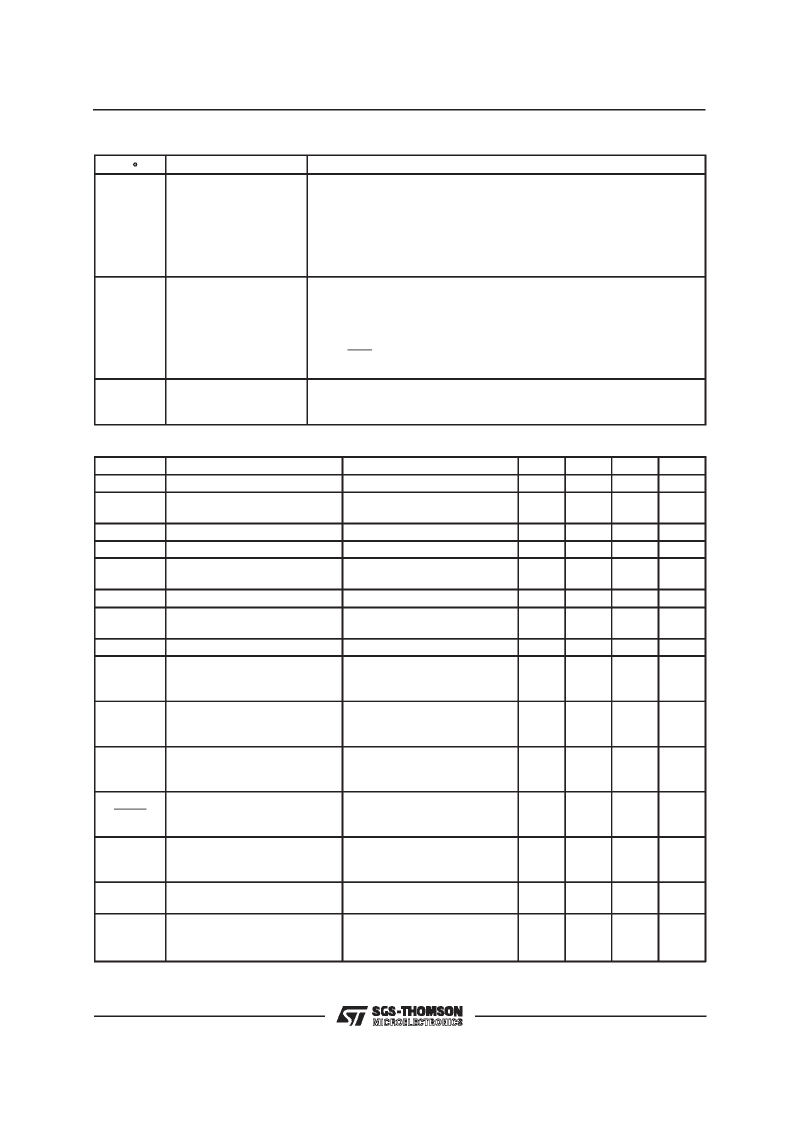
PIN FUNCTIONS
(continued)
N
°
14
Name
Function
DRIVER EMITTER
OUTPUT
Current Driver for the External Darlington. To ensure stability and precision
of T
desat
C
c
and R
9
must be used. Recommended value for R
9
is 2 K
in
order not to change the open loop gain of the system.
R
c
may be added to C
c
to obtain greater flexibility in various application
situations.
C
c
and R
c
values ranges are 1 to 100 nF and 5 to 30 K
depending on the
external darlington type.
The darlington is protected against overvoltage by means of an internal
zener available at this pin and connected to pin 14. The internal divider
R
3
/R
2
defines the limitation value given by :
15
OVERVOLTAGE LIMIT
V
ovp
=
22.5
R
3
+
5.10
3
R
2
+
22.5
16
DRIVER COLLECTOR
INPUT
The collector current of the internal driver which drives the external
darlington is supplied through this pin. Then the external resistor R
6
limits
the maximum current supplied to the base of the external darlington.
ELECTRICAL CHARACTERISTICS
(V
S
= 14.4 V, – 40
°
C < T
j
< 125
°
C unless otherwise specified)
Symbol
V
3
I
3
Parameter
Test Conditions
Min.
3.5
5
7
Typ.
Max.
Unit
V
mA
mA
V
V
V
V
μ
A
V
V
mV
μ
A
Min Op. Voltage
Supply Current
V
3
= 6 V
V
3
= 4 V
18
25
13
28
8.2
0.6
V
S
V
Z3
V
5
Voltage Supply
Supply Clamping Zener Voltage
Input Voltage
I
Z3
= 70 mA
Low Status
High Status
V
5
= LOW
I
14
= 50 mA
I
14
= 180 mA
V
S
= 6 to 16 V
V
S
= 5.3 to 16V
V
11
= 0.5V
T = 10 to 33ms
V
S
= 5.3 to 16V
V
11
= 0.5V
T = 10 to 33ms
VS = 5.3 to 16V
V
11
= 0.5V
T = 10 to 33ms
6.8
7.5
2.5
– 400
I
5
Input Current
Darlington Driver Sat. Current
– 50
0.5
0.9
370
– 7.8
V
16–14
V
SENS
I
11C
Current Limit. Sensing Voltage
C
W
Charge Current
260
– 11.0
320
– 9.3
I
11D
CW Charge Current
0.5
0.7
1.0
μ
A
I
11C
/ I
11D
See Note 1
7.8
22.0
I
SRC
I
SENSE
Percentage of Output Current
Determining the Slow Recovery
Control Start (fig. 2), note 1
Duration of Altered Small Contr.
Ratio after SRC Function Start
(fig. 2)
External Darlington over V Prot.
Zener Voltage
Permanent Conduction Time
90
94
98.5
%
T
SRC
C
SRC
= 1
μ
F
R
7
= 62 K
0.8
s
V
Z15
I
15
= 5 mA
I
15
= 2 mA
V
5
= High
C
P
= 1
μ
F
R
7
= 62K
19
18
0.4
22.5
21.5
1.1
26
25
1.8
V
V
s
T
P
L497
4/11
相關(guān)PDF資料 |
PDF描述 |
|---|---|
| L497 | HALL EFFECT PICKUP IGNITION CONTROLLER |
| L497B | HALL EFFECT PICKUP IGNITION CONTROLLER |
| L4990 | PRIMARY CONTROLLER |
| L4990A | PRIMARY CONTROLLER |
| L4990AD | PRIMARY CONTROLLER |
相關(guān)代理商/技術(shù)參數(shù) |
參數(shù)描述 |
|---|---|
| L4981 | 制造商:未知廠家 制造商全稱:未知廠家 功能描述:L4981 功率因數(shù)校正集成電路 |
| L4981A | 功能描述:功率因數(shù)校正 IC Very High Power RoHS:否 制造商:Fairchild Semiconductor 開關(guān)頻率:300 KHz 最大功率耗散: 最大工作溫度:+ 125 C 安裝風格:SMD/SMT 封裝 / 箱體:SOIC-8 封裝:Reel |
| L4981A | 制造商:STMicroelectronics 功能描述:POWER FACTOR CORRECTOR 4981 DIP20 |
| L4981A_01 | 制造商:STMICROELECTRONICS 制造商全稱:STMicroelectronics 功能描述:POWER FACTOR CORRECTOR |
| L4981AD | 功能描述:功率因數(shù)校正 IC Very High Power RoHS:否 制造商:Fairchild Semiconductor 開關(guān)頻率:300 KHz 最大功率耗散: 最大工作溫度:+ 125 C 安裝風格:SMD/SMT 封裝 / 箱體:SOIC-8 封裝:Reel |
發(fā)布緊急采購,3分鐘左右您將得到回復(fù)。