- 您現(xiàn)在的位置:買賣IC網(wǎng) > PDF目錄383234 > L497D1 (意法半導(dǎo)體) HALL EFFECT PICKUP IGNITION CONTROLLER PDF資料下載
參數(shù)資料
| 型號: | L497D1 |
| 廠商: | 意法半導(dǎo)體 |
| 英文描述: | HALL EFFECT PICKUP IGNITION CONTROLLER |
| 中文描述: | 霍爾效應(yīng)皮卡點火控制器 |
| 文件頁數(shù): | 3/11頁 |
| 文件大小: | 106K |
| 代理商: | L497D1 |
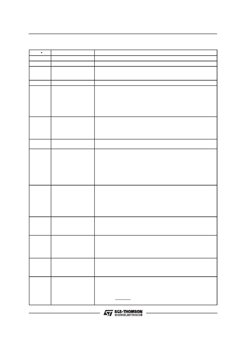
PIN FUNCTIONS
(refer to fig. 4)
N
°
1
2
3
Name
GND
Function
This pin must be connected to ground.
This pin must be connected to ground.
Supply Voltage Input. An internal 7.5 V (typ) zener zener limits the voltage
at this pin. The external resistor R
5
limits the current through the zener for
high supply voltages.
This pin must be connected to ground or left open.
Hall-effect Pickup Signal Input. This input is dwell control circuit output in
order to enable the current driving into the coil. The spark occurs at the
high-to-low transition of the hall-effect pickup signal.
Furthermore this input signal enables the slow recovery and permanent
conduction protection circuits. The input signal, supplied by the open
collector output stage of the Hall effect sensor, has a duty-cycle typically
about 70 %. V
5
is internally clamped to V
3
and ground by diodes
Open collector output which is at a low level when current flows in the
ignition coil. For high voltages protection of this output, connection to the
pin 7 zener is recommended.
In this situation R
8
must limit the zener current, too, and R
1
limits pin 6
current if RPM module pad is accidentally connected to V
S
.
A 21 V (typ) General Purpose Zener. Its current must be limited by an
external resistor.
A capacitor connected between this pin and ground sets the slope of the
dwell time variation as it rises from zero to the correct value. This occurs
after the detection of I
coll
≤
94 % I
nom
, just before the low transition of the
hall-effect signal pulse.
The duration of the slow recovery is given by :
t
src
= 12,9 R
7
C
src
(ms)
where R
7
is the biasing resistor at pin 12 (in K
) and C
src
is the delay
capacitor at pin 8 (in
μ
F).
A capacitor connected between this pin and ground determines the
intervention delay of the permanent conduction protection. After this delay
time the coil current is slowly reduced to zero.
Delay Time T
p
is given by :
T
p
=16 C
p
R
7
(ms)
where R
7
is the biasing resistor at pin 12 (in K
) and C
P
is the delay
capacitor at pin 9 (in
μ
F).
A capacitor C
T
connected between this pin and ground is charged when the
HAll effect output is High and is discharged at the High to Low transition of
the Hall effect signal.
The recommended value is 100 nF using a 62 K
resistor at pin 12.
The average voltage on the capacitor CW connected between this pin and
ground depends on the motor speed and the voltage supply. The
comparison between V
CW
and V
CT
voltage determines the timing for the
dwell control. For the optimized operation of the device C
T
= C
W
; the
recommended value is 100 nF using a 62 K
resistor at pin 12.
A resistor connected between this pin and ground sets the internal current
used to drive the external capacitors of the dwell control
(pin 10 and 11) permanent conduction protection (pin 9) and slow recovery
time (pin 8). The recommended value is 62 K
.
Connection for the Coil Current Limitation. The current is measured on the
sensing resitor R
S
and taken through the divider R
10
/R
11
. The current
limitation value is given by :
SIGNAL GND
POWER SUPPLY
4
5
N.C.
HALL-EFFECT INPUT
6
RPM OUTPUT
7
AUX. ZENER
8
RECOVERY TIME
9
MAX CONDUCTION
TIME
10
DWELL CONTROL
TIMER
11
DWELL CONTROL
12
BIAS CURRENT
13
CURRENT SENSING
I
sens
=
0.32
R
10
+
R
11
R
S
R
11
L497
3/11
相關(guān)PDF資料 |
PDF描述 |
|---|---|
| L497 | HALL EFFECT PICKUP IGNITION CONTROLLER |
| L497B | HALL EFFECT PICKUP IGNITION CONTROLLER |
| L4990 | PRIMARY CONTROLLER |
| L4990A | PRIMARY CONTROLLER |
| L4990AD | PRIMARY CONTROLLER |
相關(guān)代理商/技術(shù)參數(shù) |
參數(shù)描述 |
|---|---|
| L4981 | 制造商:未知廠家 制造商全稱:未知廠家 功能描述:L4981 功率因數(shù)校正集成電路 |
| L4981A | 功能描述:功率因數(shù)校正 IC Very High Power RoHS:否 制造商:Fairchild Semiconductor 開關(guān)頻率:300 KHz 最大功率耗散: 最大工作溫度:+ 125 C 安裝風(fēng)格:SMD/SMT 封裝 / 箱體:SOIC-8 封裝:Reel |
| L4981A | 制造商:STMicroelectronics 功能描述:POWER FACTOR CORRECTOR 4981 DIP20 |
| L4981A_01 | 制造商:STMICROELECTRONICS 制造商全稱:STMicroelectronics 功能描述:POWER FACTOR CORRECTOR |
| L4981AD | 功能描述:功率因數(shù)校正 IC Very High Power RoHS:否 制造商:Fairchild Semiconductor 開關(guān)頻率:300 KHz 最大功率耗散: 最大工作溫度:+ 125 C 安裝風(fēng)格:SMD/SMT 封裝 / 箱體:SOIC-8 封裝:Reel |
發(fā)布緊急采購,3分鐘左右您將得到回復(fù)。