- 您現在的位置:買賣IC網 > PDF目錄383157 > ISL6559CB-T (INTERSIL CORP) Multi-Phase PWM Controller PDF資料下載
參數資料
| 型號: | ISL6559CB-T |
| 廠商: | INTERSIL CORP |
| 元件分類: | 穩(wěn)壓器 |
| 英文描述: | Multi-Phase PWM Controller |
| 中文描述: | SWITCHING CONTROLLER, 1000 kHz SWITCHING FREQ-MAX, PDSO28 |
| 封裝: | PLASTIC, MS-013-AE, SOIC-28 |
| 文件頁數: | 13/21頁 |
| 文件大小: | 606K |
| 代理商: | ISL6559CB-T |
13
FN9084.8
December 29, 2004
Over-Voltage Protection
When the output of the differential amplifier (VDIFF) reaches
2.2V, PGOOD immediately goes low indicating a fault. Two
protective actions are taken by the ISL6559 to protect the
microprocessor load.
First, all PWM outputs are commanded low. Directing the
Intersil drivers to turn on the lower MOSFETs; shunting the
output to ground preventing any further increase in output
voltage. The PWM outputs remain low until VDIFF falls to the
programmed DAC level at which time they go into a high-
impedance state. The Intersil drivers respond by turning off
both upper and lower MOSFETs. If the over-voltage
condition reoccurs, the ISL6559 will again command the
lower MOSFETs to turn on. The ISL6559 will continue to
protect the load in this fashion as long as the over-voltage
repeats.
Second, the OVP pin pulls to VCC and can deliver 100mA
into the gate of either a MOSFET or SCR placed across the
input voltage (V
IN
) and V
OUT
. Turning on the MOSFET or
SCR collapses the power rail and causes a fuse placed
further up stream to blow. The fuse must be sized such that
the MOSFET or SCR will not overheat before the fuse blows.
Once an over-voltage condition is detected, normal PWM
operation ceases and PGOOD remains low until the
ISL6559 is reset. Cycling the voltage on EN below 1.23V or
the bias to VCC below the POR-falling threshold will reset
the controller.
Over-Current Protection
The ISL6559 takes advantage of the proportionality between
the load current and the average current, I
AVG
, to detect an
over-current condition. See the
Channel-Current Balance
section for more detail on how the average current is
created. The average current is continually compared with a
constant 90
μ
A reference current. Once the average current
exceeds the reference current, the comparator triggers the
converter to shutdown. The POR circuit places all PWM
signals in a high-impedance state which commands the
drivers to turn off both upper and lower MOSFETs. PGOOD
pulls low and the system remains in this state while the
controller counts 2048 phase clock cycles. This is followed
by a soft-start attempt (see
Soft-Start
).
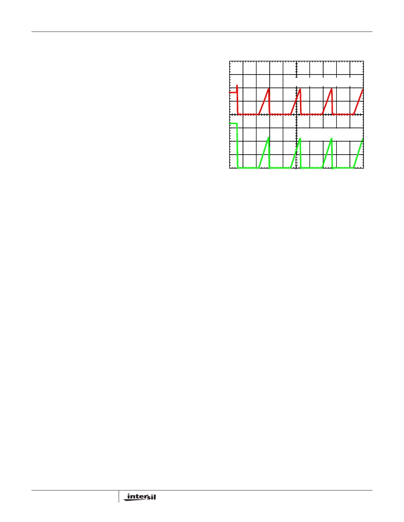
During the soft-start interval, the over-current protection
circuitry remains active. As the output voltage ramps up, if an
over-current condition is detected, the ISL6559 immediately
places all PWM signals in a high-impedance state. The
ISL6559 repeats the 2048-cycle wait period and follows with
another soft-start attempt, as shown in
Figure 11. This hiccup mode of operation repeats up to
seven times. On the eighth soft-start attempt, the part
latches off. Once latched off, the ISL6559 can only be reset
when the voltage on EN is brought below 1.23V or VCC is
brought below the POR falling threshold. Upon completion of
a successful soft-start attempt, operation will continue as
normal, PGOOD will return high, and the OC latch counter is
reset.
During VID-on-the-fly transitions, the OC comparator output
is blanked. The quality and mix of output capacitors used in
different applications leads to a wide output capacitance
range. Depending upon the magnitude and direction of the
VID change, the change in voltage across the output
capacitors could result in significant current flow. Summing
this instantaneous current with the load current already
present could drive the average current above the reference
current level and cause an OC trip during the transition. By
blanking the OC comparator during the VID-on-the-fly
transition, nuisance tripping is avoided.
General Design Guide
This design guide is intended to provide a high-level
explanation of the steps necessary to create a multi-phase
power converter. It is assumed that the reader is familiar with
many of the basic skills and techniques referenced below. In
addition to this guide, Intersil provides complete reference
designs that include schematics, bills of materials, and
example board layouts for all common microprocessor
applications.
0A
0V
5ms/DIV
OUTPUT VOLTAGE,
500mV/DIV
OUTPUT CURRENT, 20A/DIV
FIGURE 11. OVERCURRENT BEHAVIOR IN HICCUP MODE
ISL6559
相關PDF資料 |
PDF描述 |
|---|---|
| ISL6559CR-T | Multi-Phase PWM Controller |
| ISL6559CRZ | Multi-Phase PWM Controller |
| ISL6559CRZ-T | Multi-Phase PWM Controller |
| ISL6559 | Multi-Phase PWM Controller |
| ISL6559CB | Multi-Phase PWM Controller |
相關代理商/技術參數 |
參數描述 |
|---|---|
| ISL6559CBZ | 功能描述:電流型 PWM 控制器 2 TO 4 PHS BUCK CNTRLR 2 8LD RoHS:否 制造商:Texas Instruments 開關頻率:27 KHz 上升時間: 下降時間: 工作電源電壓:6 V to 15 V 工作電源電流:1.5 mA 輸出端數量:1 最大工作溫度:+ 105 C 安裝風格:SMD/SMT 封裝 / 箱體:TSSOP-14 |
| ISL6559CBZ-T | 功能描述:電流型 PWM 控制器 2 TO 4 PHS BUCK CNTRLR 2 8LD RoHS:否 制造商:Texas Instruments 開關頻率:27 KHz 上升時間: 下降時間: 工作電源電壓:6 V to 15 V 工作電源電流:1.5 mA 輸出端數量:1 最大工作溫度:+ 105 C 安裝風格:SMD/SMT 封裝 / 箱體:TSSOP-14 |
| ISL6559CR | 功能描述:IC REG CTRLR BUCK PWM VM 32-QFN RoHS:否 類別:集成電路 (IC) >> PMIC - 穩(wěn)壓器 - DC DC 切換控制器 系列:- 標準包裝:4,000 系列:- PWM 型:電壓模式 輸出數:1 頻率 - 最大:1.5MHz 占空比:66.7% 電源電壓:4.75 V ~ 5.25 V 降壓:是 升壓:無 回掃:無 反相:無 倍增器:無 除法器:無 Cuk:無 隔離:無 工作溫度:-40°C ~ 85°C 封裝/外殼:40-VFQFN 裸露焊盤 包裝:帶卷 (TR) |
| ISL6559CR-T | 功能描述:IC REG CTRLR BUCK PWM VM 32-QFN RoHS:否 類別:集成電路 (IC) >> PMIC - 穩(wěn)壓器 - DC DC 切換控制器 系列:- 標準包裝:4,000 系列:- PWM 型:電壓模式 輸出數:1 頻率 - 最大:1.5MHz 占空比:66.7% 電源電壓:4.75 V ~ 5.25 V 降壓:是 升壓:無 回掃:無 反相:無 倍增器:無 除法器:無 Cuk:無 隔離:無 工作溫度:-40°C ~ 85°C 封裝/外殼:40-VFQFN 裸露焊盤 包裝:帶卷 (TR) |
| ISL6559CRZ | 功能描述:電流型 PWM 控制器 2 TO 4 PHS BUCK CNTRLR 32L 5X5 MLFP RoHS:否 制造商:Texas Instruments 開關頻率:27 KHz 上升時間: 下降時間: 工作電源電壓:6 V to 15 V 工作電源電流:1.5 mA 輸出端數量:1 最大工作溫度:+ 105 C 安裝風格:SMD/SMT 封裝 / 箱體:TSSOP-14 |
發(fā)布緊急采購,3分鐘左右您將得到回復。