- 您現(xiàn)在的位置:買賣IC網(wǎng) > Datasheet目錄40 > ISL6174IRZ (Intersil)IC CIRC BREAKER DUAL LV 28-QFN Datasheet資料下載
參數(shù)資料
| 型號: | ISL6174IRZ |
| 廠商: | Intersil |
| 文件頁數(shù): | 1/16頁 |
| 文件大?。?/td> | 346K |
| 描述: | IC CIRC BREAKER DUAL LV 28-QFN |
| 標(biāo)準(zhǔn)包裝: | 60 |
| 類型: | 熱交換控制器 |
| 應(yīng)用: | 通用 |
| 內(nèi)部開關(guān): | 無 |
| 電源電壓: | 2.25 V ~ 3.63 V |
| 工作溫度: | -40°C ~ 85°C |
| 安裝類型: | 表面貼裝 |
| 封裝/外殼: | 28-VFQFN 裸露焊盤 |
| 供應(yīng)商設(shè)備封裝: | 28-QFN 裸露焊盤(5x5) |
| 包裝: | 管件 |

1
?/DIV>
FN6830.0
ISL6174
Dual Low Voltage Circuit Breaker
This IC targets dual voltage hot swap applications across the
+2.5V to +3.3V (nominal) bias supply voltage range with a
second lower voltage rail down to less than 1V where a circuit
breaker response to an over current event is preferred.
It features a charge pump for driving external N-Channel
MOSFETs, accurate programmable circuit breaker current
thresholds and delay output undervoltage monitoring and
reporting and adjustable soft-start.
The circuit breaker current level (I
CB
) for each rail is set by
two external resistors, and for each rail a delay (t
CB)
is set by
an external capacitor on the TCB pin. After t
CB
has expired,
the IC then quickly pulls down the associated GATE(s)
output turning off its external FET(s).
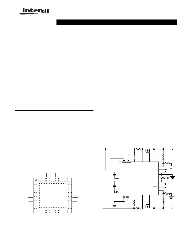
Pinout
ISL6174
(28 LD QFN)
TOP VIEW
Features
" Fast Circuit Breaker Quickly Responds to Overcurrent
Fault Conditions
" Less than 1祍 Response Time to Dead Short
" Programmable Circuit Breaker Level and Delay
" Two Levels of Overcurrent Detection Provide Fast
Response to Varying Fault Conditions
" Overcurrent Circuit Breaker and Fault Isolation Functions
" Adjustable Circuit Breaker Threshold as Low as 20mV
" Adjustable Voltage Ramp-up for In-Rush Protection
During Turn-On
" Rail Independent Control, Monitoring and Reporting I/O
" Dual Supply Hot Swap Power Distribution Control to <1V
" Charge Pump Allows the Use of N-Channel MOSFETs
" QFN Package:
- Compliant to JEDEC PUB95 MO-220
QFN - Quad Flat No Leads - Package Outline
- Near Chip Scale Package Footprint, Which Improves
PCB Efficiency and has a Thinner Profile
" Pb-Free (RoHS Compliant)
Applications
" Power Supply Sequencing, Distribution and Control
" Hot Swap / Electronic Circuit Breaker Circuits
Ordering Information
PART NUMBER
(Note)
PART
MARKING
TEMP.
RANGE
(癈)
PACKAGE
(Pb-Free)
PKG.
DWG. #
ISL6174IRZ*
ISL6174 IRZ -40 to +85 28 Ld 5x5 QFN L28.5x5
ISL617XEVAL1Z Evaluation Platform
*Add
-T
suffix for tape and reel. Please refer to TB347 for details on
reel specifications.
NOTE: These Intersil Pb-free plastic packaged products employ
special Pb-free material sets, molding compounds/die attach materials,
and 100% matte tin plate plus anneal (e3 termination finish, which is
RoHS compliant and compatible with both SnPb and Pb-free soldering
operations). Intersil Pb-free products are MSL classified at Pb-free
peak reflow temperatures that meet or exceed the Pb-free
requirements of IPC/JEDEC J STD-020.
1
2
3
4
5
6
7
21
20
19
18
17
16
15
28 27 26 25 24 23 22
8 9 10 11 12 13 14
SNS2
VO2
SS2
GT2
FLT2
PG2
TCB2
SNS1
VO1
SS1
GT1
FLT1
PG1
TCB1
V1(IN)
V2(IN)
V1(OUT)
V2(OUT)
R
SNS
1
R
SNS
2
FIGURE 1. TYPICAL APPLICATION
ISL6174
EN1
EN2
BIAS
CPQ+
CPQ-
CPVDD
PGND
GND
TCB1TCB2 VS2 SNS2 GT2 VO2
UV2
PG2
FLT2
FLT1
PG1
SS1
SS2
OCREF
GT1 VO1
UV1
VS1 SNS1
Data Sheet
CAUTION: These devices are sensitive to electrostatic discharge; follow proper IC Handling Procedures.
1-888-INTERSIL or 1-888-468-3774 | Intersil (and design) is a registered trademark of Intersil Americas Inc.
Copyright Intersil Americas Inc. 2008. All Rights Reserved
All other trademarks mentioned are the property of their respective owners.
December 19, 2008
相關(guān)PDF資料 |
PDF描述 |
|---|---|
| ISL61861DCBZ | IC USB PWR CTRLR 3A 8SOIC |
| ISL6402IR | IC REG TRPL BCK/LINEAR 28-QFN |
| ISL6413IRZ-TK | IC REG TRPL BCK/LINEAR 24-QFN |
| ISL6432CB-T | IC REG QD BCK/LINEAR 16-SOIC |
| ISL6521CBZS2698 | IC REG QD BCK/LINEAR 16-SOIC |
相關(guān)代理商/技術(shù)參數(shù) |
參數(shù)描述 |
|---|---|
| ISL6174IRZ-T | 功能描述:IC CIRC BREAKER DUAL LV 28-QFN RoHS:是 類別:集成電路 (IC) >> PMIC - 熱交換 系列:- 產(chǎn)品培訓(xùn)模塊:Obsolescence Mitigation Program 標(biāo)準(zhǔn)包裝:100 系列:- 類型:熱插拔開關(guān) 應(yīng)用:通用 內(nèi)部開關(guān):是 電流限制:可調(diào) 電源電壓:9 V ~ 13.2 V 工作溫度:-40°C ~ 150°C 安裝類型:表面貼裝 封裝/外殼:10-WFDFN 裸露焊盤 供應(yīng)商設(shè)備封裝:10-TDFN-EP(3x3) 包裝:管件 |
| ISL617XEVAL1Z | 制造商:INTERSIL 制造商全稱:Intersil Corporation 功能描述:Dual Low Voltage Circuit Breaker |
| ISL6185 | 制造商:INTERSIL 制造商全稱:Intersil Corporation 功能描述:Dual USB Port Power Supply Controller |
| ISL6185_11 | 制造商:INTERSIL 制造商全稱:Intersil Corporation 功能描述:Dual USB Port Power Supply Controller 2.5V to 5V Operating Range |
| ISL61851ACBZ | 功能描述:熱插拔功率分布 DL USB HOTSWAP W/INT FET-EN HI 8LD RoHS:否 制造商:Texas Instruments 產(chǎn)品:Controllers & Switches 電流限制: 電源電壓-最大:7 V 電源電壓-最小:- 0.3 V 工作溫度范圍: 功率耗散: 安裝風(fēng)格:SMD/SMT 封裝 / 箱體:MSOP-8 封裝:Tube |
發(fā)布緊急采購,3分鐘左右您將得到回復(fù)。