- 您現(xiàn)在的位置:買賣IC網(wǎng) > PDF目錄360914 > IQX320-10PP391I User Programmable Special Function ASIC PDF資料下載
參數(shù)資料
| 型號: | IQX320-10PP391I |
| 英文描述: | User Programmable Special Function ASIC |
| 中文描述: | 用戶可編程ASIC的特殊功能 |
| 文件頁數(shù): | 13/65頁 |
| 文件大小: | 620K |
| 代理商: | IQX320-10PP391I |
第1頁第2頁第3頁第4頁第5頁第6頁第7頁第8頁第9頁第10頁第11頁第12頁當前第13頁第14頁第15頁第16頁第17頁第18頁第19頁第20頁第21頁第22頁第23頁第24頁第25頁第26頁第27頁第28頁第29頁第30頁第31頁第32頁第33頁第34頁第35頁第36頁第37頁第38頁第39頁第40頁第41頁第42頁第43頁第44頁第45頁第46頁第47頁第48頁第49頁第50頁第51頁第52頁第53頁第54頁第55頁第56頁第57頁第58頁第59頁第60頁第61頁第62頁第63頁第64頁第65頁
IQX Family Data Sheet
June 2000
Revision 5.0
13
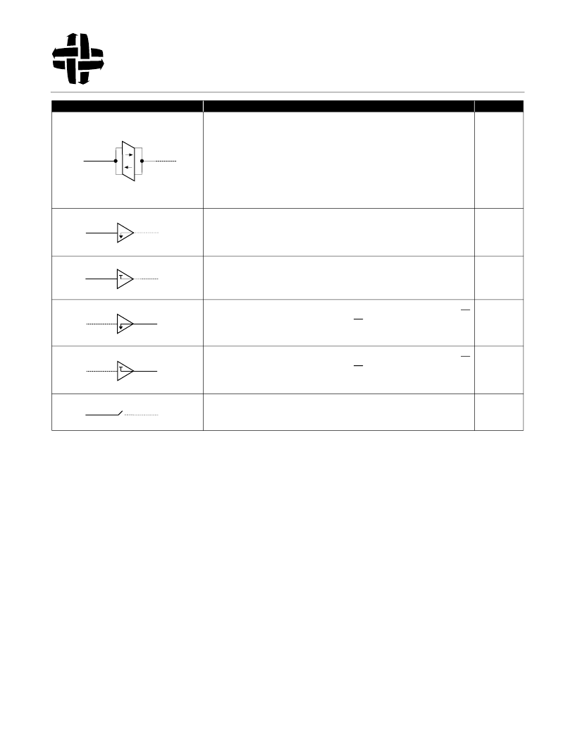
Bus Repeater
- In the Bus Repeater mode, the I/O Port behaves as a wire (with a non-zero
propagation delay). This unique feature patented by I-Cube incorporates a self-sensing circuit
to determne signal direction and does not require a direction control signal.
When multiple I/O Ports, configured as “Bus Repeater”, are connected together through the
Switch Matrix to forma single internal node, an (open collector or tristatable) external signal
appearing at any one of the I/O Ports gets repeated (or broadcast) to other I/O Ports.
The Bus Repeater mode requires a pull-up current source (see section on “Programmable
Pull-Up Current”) to operate properly. For more details, refer to the Technical Note: “The Bus
Repeater Mode.”
BR
Array Side Force 0
- In this input mode, the Switch Matrix line is forced low (logic 0),
regardless of the signal on the corresponding I/O Port. In this mode an optional input enable
(IE) can be selected. Either polarity can be selected for IE. The default level is a logic 1.
A0
Array Side Force 1
- In this input mode, the Switch Matrix line is forced high (logic 1),
regardless of the signal on the corresponding I/O Port. In this mode an optional input enable
(IE) can be selected. Either polarity can be selected for IE. The default level is a logic 1.
A1
Pin Side Force 0
- In this output mode, the I/O Port pin is forced low (logic 0), regardless of
the signal on the corresponding Switch Matrix line. In this mode an optional output enable (OE)
can be selected. Either polarity can be selected for OE. The default level is a logic 0.
F0
Pin Side Force 1
- In this output mode, the I/O Port pin is forced high (logic 1), regardless of
the signal on the corresponding Switch Matrix line. In this mode an optional output enable (OE)
can be selected. Either polarity can be selected for OE. The default level is a logic 0.
F1
No Connect
- In this mode, the I/O Port pin is isolated fromthe Switch Matrix. This is done by
tristating both the input and output part of the I/O buffer.
NC
Symbol
I/O Port Function
Mnemonic
Table 1. Summary of Programmable I/O Attributes for IQX Devices (Continued)
Px
Ax
Px
Ax
Px
Ax
Px
Ax
Px
Ax
Px
Ax
Powered by ICminer.com Electronic-Library Service CopyRight 2003
相關PDF資料 |
PDF描述 |
|---|---|
| IQX320-12PP391 | User Programmable Special Function ASIC |
| IQX320-12PP391I | User Programmable Special Function ASIC |
| IQX320-15PP391 | User Programmable Special Function ASIC |
| IQX320-15PP391I | User Programmable Special Function ASIC |
| IQX320-7PP391 | User Programmable Special Function ASIC |
相關代理商/技術參數(shù) |
參數(shù)描述 |
|---|---|
| IQXO-22C-24.0 | 制造商:IQD Frequency Products 功能描述:OSCILLATOR CRYSTAL |
| IQXO-22C-32MHZ | 制造商:IQD Frequency Products 功能描述:OSCILLATOR CRYSTAL |
| IQXO-22C-4.0 | 制造商:IQD Frequency Products 功能描述:OSCILLATOR CRYSTAL |
| IQXO-22C-50.0 | 制造商:IQD Frequency Products 功能描述:OSCILLATOR CRYSTAL |
| IQXO-331-100.0MHz | 制造商:IQD Frequency Products 功能描述:CRYSTAL OSCILLATOR 100.000000MHZ |
發(fā)布緊急采購,3分鐘左右您將得到回復。