- 您現(xiàn)在的位置:買賣IC網(wǎng) > PDF目錄360856 > IMS30 Dual outputs 5V & 3.3V ; 3.3V & 1.8V PDF資料下載
參數(shù)資料
| 型號: | IMS30 |
| 英文描述: | Dual outputs 5V & 3.3V ; 3.3V & 1.8V |
| 中文描述: | 5V的雙輸出 |
| 文件頁數(shù): | 4/11頁 |
| 文件大?。?/td> | 1153K |
| 代理商: | IMS30 |
Input Transient Voltage Protection
A built-in suppressor diode provides effective protection
against input transients which may be caused for example
by short-circuits accross the input lines where the network
inductance may cause high energy pulses.
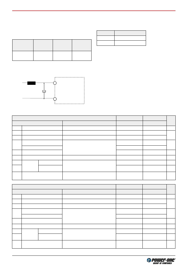
Table 3: Built-in transient voltage suppressor
Type
Breakdown
voltage
V
BR nom
[V]
Peak power
at 1 ms
P
P
[W]
Peak pulse
current
I
PP
[A]
48 IMS 30
100
600
4.1
For very high energy transients as for example to achieve
IEC/EN 61000-4-5 or ETR 283 (19 Pfl1) compliance (as per
table:
Electromagnetic Immunity
) an external inductor and
capacitor are required.
L
V+
Vi+
Vi–
C
V–
Module
+
04009
1
2
Fig. 4
Example for external circuitry to comply with
IEC/EN 61000-4-5 or ETR 283 (19 Pfl1) (48 IMS 30 types).
Table 4: Components for external circuitry to comply with
IEC/EN 61000-4-5, level 2 or ETR 283 (19Pfl1)
(48 IMS types).
Circuit Ref.
48 IMS 30
L
150
uH
C
100
uF, 100 V, 85
C
Reverse Polarity Protection at the Input
The built-in suppressor diode also provides for reverse po-
larity protection at the input by conducting current in the re-
verse direction. An external fuse is required to limit this cur-
rent:
48 IMS 30: 3.15 A (F3.15A)
Electrical Ouput Data
Table 5a: Output data.
Model 48IMS30-0503
-9G
3.3 V
5.1 V
Characteristics
Conditions
min
typ max
min
typ max
Unit
U
o1
Output voltage
U
i nom
,
I
o
= 0.5
I
o nom
3.25
3.35
5.00
5.20
V
I
o nom
Output current
U
i min
...
U
i max
A
I
oL
Current limit
1
U
i nom
9
U
o
Line regulation
U
i min
...
U
i max
I
o
= (0...1)
I
o nom
+/-0.5
u
o1
Output voltage noise
2
50
75
mV
pp
uF
C
o ext
Admissible capacitive load
2000
2000
u
o d
Dynamic
load
regulation
Voltage deviation
U
i nom
I
o nom
250
250
mV
t
d
Recovery time
1
/
2
I
o nom
1
1
ms
Uo
Temperature coefficient
U
o
/
T
C
Table 5b: Output data.
U
i nom
,
I
o nom
T
C min
...
T
C max
0.02
0.02
%/K
1
The current limit is primary side controlled.
2
BW = 20 MHz
0
6
0
3.5
6
See Fig. 6
Load regulation
+/-0.5
%
+/-1
4/11
Model 48IMS30-0302
-9G
3.3 V
1.8 V
Characteristics
Conditions
min typ max
min typ max
Unit
U
o1
Output voltage
U
i nom
,
I
o
= 0.5
I
o nom
3.25
3.35
1.83
1.77
V
I
o nom
Output current
U
i min
...
U
i max
A
I
oL
Current limit
1
U
i no
m
6
U
i min
...
U
i max
I
o
= (0...1)
I
o nom
U
o
Line regulation
+/-0.5
u
o1
Output voltage noise
2
50
50
mV
pp
uF
C
o ext
Admissible capacitive load
2000
2000
u
o d
Dynamic
load
regulation
Voltage deviation
U
i nom
I
o nom
250
150
mV
t
d
Recovery time
1
/
2
I
o nom
1
1
ms
Uo
Temperature coefficient
U
o
/
T
C
U
i nom
,
I
o nom
T
C min
...
T
C max
0.02
0.02
%/K
0
4
0
5
7
See Fig. 6
Load regulation
+/-0.5
%
+/-3
相關(guān)PDF資料 |
PDF描述 |
|---|---|
| IMS6 | 6 Watt SMD and through hole DC/DC converters |
| IMS7 | Standard Metal Shell Nano Strip Connector |
| IMSA100-G17M | Digital Filter |
| IMSA100-G21I | Digital Filter |
| IMSA100-G21M | Digital Filter |
相關(guān)代理商/技術(shù)參數(shù) |
參數(shù)描述 |
|---|---|
| IMS-30-G | 制造商:Samtec Inc 功能描述:MALE .100 IDC CABLE CONNECTOR - Bulk 制造商:Samtec Inc 功能描述:RECEPTACLE, 2.54MM, IDC / IDT, 30WAY |
| IMS-31-G | 制造商:Samtec Inc 功能描述:MALE .100 IDC CABLE CONNECTOR - Bulk |
| IMS-31-T | 制造商:Samtec Inc 功能描述:MALE .100 IDC CABLE CONNECTOR - Bulk |
| IMS320DM6467CCUTD7 | 制造商:Texas Instruments 功能描述: |
| IMS-32-G | 制造商:Samtec Inc 功能描述:MALE .100 IDC CABLE CONNECTOR - Bulk |
發(fā)布緊急采購,3分鐘左右您將得到回復(fù)。