- 您現(xiàn)在的位置:買賣IC網(wǎng) > PDF目錄377487 > IDT821064PQF (INTEGRATED DEVICE TECHNOLOGY INC) QUAD PROGRAMMABLE PCM CODEC WITH GCI INTERFACE PDF資料下載
參數(shù)資料
| 型號: | IDT821064PQF |
| 廠商: | INTEGRATED DEVICE TECHNOLOGY INC |
| 元件分類: | 編解碼器 |
| 英文描述: | QUAD PROGRAMMABLE PCM CODEC WITH GCI INTERFACE |
| 中文描述: | A/MU-LAW, PROGRAMMABLE CODEC, PQFP64 |
| 封裝: | PLASTIC, QFP-64 |
| 文件頁數(shù): | 25/33頁 |
| 文件大小: | 510K |
| 代理商: | IDT821064PQF |
第1頁第2頁第3頁第4頁第5頁第6頁第7頁第8頁第9頁第10頁第11頁第12頁第13頁第14頁第15頁第16頁第17頁第18頁第19頁第20頁第21頁第22頁第23頁第24頁當(dāng)前第25頁第26頁第27頁第28頁第29頁第30頁第31頁第32頁第33頁

25
INDUSTRIAL TEMPERATURE RANGE
IDT821064 QUAD PROGRAMMABLE PCM CODEC WITH GCI INTERFACE
DSH[3:0] = 1011: 22 ms;
DSH[3:0] = 1100: 24 ms;
DSH[3:0] = 1101: 26 ms;
DSH[3:0] = 1110: 28 ms;
DSH[3:0] = 1111: 30 ms.
GK Debounce bits GK[3:0] set the debounce time of SI2 input from SLIC for corresponding channel.
GK[3:0] = 0000: 0 ms (default);
GK[3:0] = 0001: 2 ms;
GK[3:0] = 0010: 4 ms;
GK[3:0] = 0011: 6 ms;
GK[3:0] = 0100: 8 ms;
GK[3:0] = 0101: 10 ms;
GK[3:0] = 0110: 12 ms;
GK[3:0] = 0111: 14 ms;
GK[3:0] = 1000: 16 ms;
GK[3:0] = 1001: 18 ms;
GK[3:0] = 1010: 20 ms;
GK[3:0] = 1011: 22 ms;
GK[3:0] = 1100: 24 ms;
GK[3:0] = 1101: 26 ms;
GK[3:0] = 1110: 28 ms;
GK[3:0] = 1111: 30 ms;
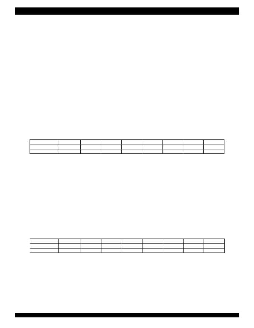
4. A/D Gain, D/A Gain, Power Down and PCM Receive Path Cutoff (08H/88H),Read/Write
Channel Power Down bit (PD) selects the operation mode on corresponding channel:
PD = 0: the corresponding channel is in normal operation;
PD = 1: the corresponding channel is powered down (default).
PCMCT bit determines the operation of PCM Receive Path on corresponding channel:
PCMCT = 0: PCM Receive Path is in normal operation (default);
PCMCT = 1: PCM Receive Path is cut off.
A/D Gain bit (GAD) sets the gain of analog A/D for corresponding channel:
GAD = 0: 0 dB (default);
GAD = 1: +6 dB.
D/A Gain bit (GDA) sets the gain of analog D/A for corresponding channel:
GDA = 0: 0 dB (default);
GDA = 1: -6 dB.
Attention: The lower 4 bits of the I/O data byte that follows this write-command (88H) must be '0000' to ensure proper operation.
5. Tone Generator Enable (09H/89H), Read/Write
TEN1 = 0: Tone1 generator is disabled (default);
TEN1 = 1: Tone1 generator is enabled.
TEN0 = 0: Tone0 generator is disabled (default);
TEN0 = 1: Tone0 generator is enabled.
Attention: The b2 and b3 of the I/O data byte that follows this write-command (89H) must be '11' to ensure proper operation.
b7
R
/W
PD
b6
0
b5
0
GAD
b4
0
GDA
b3
1
0
b2
0
0
b1
0
0
b0
0
0
Command
I/O data
PCMCT
b7
R
/W
R
b6
0
R
b5
0
R
b4
0
R
b3
1
1
b2
0
1
b1
0
b0
1
Command
I/O data
TEN1
TEN0
相關(guān)PDF資料 |
PDF描述 |
|---|---|
| IDT821068 | OCTAL PROGRAMMABLE PCM CODEC |
| IDT821068PX | OCTAL PROGRAMMABLE PCM CODEC |
| IDT821621 | LONG HAUL SLIC |
| IDT821621J | LONG HAUL SLIC |
| IDT82P2281 | Single T1/E1/J1 Long Haul Short Haul Transceiver |
相關(guān)代理商/技術(shù)參數(shù) |
參數(shù)描述 |
|---|---|
| IDT821068 | 制造商:IDT 制造商全稱:Integrated Device Technology 功能描述:OCTAL PROGRAMMABLE PCM CODEC |
| IDT821068PX | 制造商:IDT 制造商全稱:Integrated Device Technology 功能描述:OCTAL PROGRAMMABLE PCM CODEC |
| IDT821621 | 制造商:IDT 制造商全稱:Integrated Device Technology 功能描述:LONG HAUL SLIC |
| IDT821621J | 制造商:IDT 制造商全稱:Integrated Device Technology 功能描述:LONG HAUL SLIC |
| IDT8217LP35P | 制造商:Integrated Device Technology Inc 功能描述: |
發(fā)布緊急采購,3分鐘左右您將得到回復(fù)。