- 您現(xiàn)在的位置:買賣IC網(wǎng) > PDF目錄370725 > HV3-2405E-5 (Harris Corporation) World-Wide Single Chip Power Supply PDF資料下載
參數(shù)資料
| 型號(hào): | HV3-2405E-5 |
| 廠商: | Harris Corporation |
| 英文描述: | World-Wide Single Chip Power Supply |
| 中文描述: | 環(huán)球單片電源 |
| 文件頁數(shù): | 2/14頁 |
| 文件大小: | 573K |
| 代理商: | HV3-2405E-5 |

5-16
Specifications HV-2405E
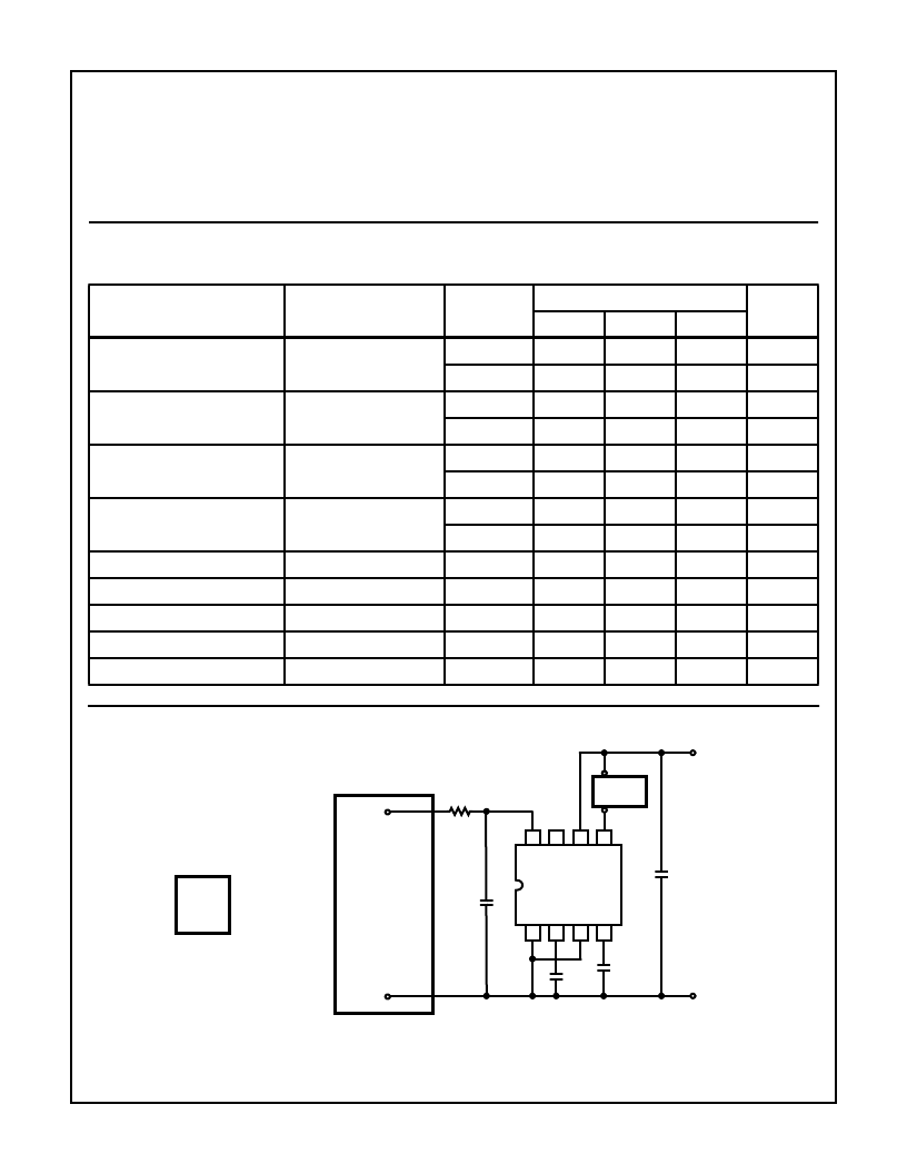
Test Circuit
Absolute Maximum Ratings
Thermal Information
Voltage Between Pin 1 and 8, Peak
. . . . . . . . . . . . . . . . . . . . . . . . ±
500V
Voltage Between Pin 2 and 6 . . . . . . . . . . . . . . . . . . . . . . . . . . . 15V
Input Current, Peak . . . . . . . . . . . . . . . . . . . . . . . . . . . . . . . . . . . 2A
Output Current . . . . . . . . . . . . . . . . . . . . . . . . . . . . . . . . . . . .100mA
Output Voltage . . . . . . . . . . . . . . . . . . . . . . . . . . . . . . . . . . . . . . 34V
Thermal Resistance
Plastic DIP. . . . . . . . . . . . . . . . . . . . . . . . . . . . . . . . . . . 150
o
C/W
Maximum Junction Temperature. . . . . . . . . . . . . . . . . . . . . . +150
o
C
Storage Temperature Range. . . . . . . . . . . . . . . . . .-65
o
C to +150
o
C
θ
JA
CAUTION: Stresses above those listed in “Absolute Maximum Ratings” may cause permanent damage to the device. This is a stress only rating and operation
of the device at these or any other conditions above those indicated in the operational sections of this specification is not implied.
Electrical Specifications
Unless Otherwise Specified: V
IN
= 264Vms at 50Hz, C1 = 0.05
μ
F, C2 = 470
μ
F, C4 = 1
μ
F, V
OUT
= 5V,
I
OUT
= 50mA, Source Impedance R
1
= 150
. Parameters are Guaranteed at the Specific V
IN
and
Frequency Conditions, Unless Otherwise Specified. See test circuit for Component Location.
PARAMETER
CONDITIONS
TEMP
HV-2405E-5/-9
UNITS
MIN
TYP
MAX
Output Voltage (At Preset 5V)
V
REF
= 0V
DC
+25
o
C
4.75
5.0
5.25
V
Full
4.65
5.0
5.35
V
Output Voltage (At Preset 24V)
V
REF
= 19V
DC
+25
o
C
22.8
24.0
25.2
V
Full
22.32
24.0
25.68
V
Line Regulation
80Vrms to 264Vrms
+25
o
C
-
10
20
mV
Full
-
15
40
mV
Load Regulation
(I
OUT
= 5mA to 50mA)
+25
o
C
-
-
20
mV
Full
-
-
40
mV
Output Current
Full
50
-
-
mA
Output Ripple (Vp-p)
Full
-
24
-
mV
Short Circuit Current Limit
Full
-
70
-
mA
Output Voltage TC
Full
-
0.02
-
%/
o
C
Quiescent Current Post Regulator
11V
DC
to 30V
DC
on Pin 2
+25
o
C
-
2
-
mA
1
2
3
4
8
7
6
5
DUT
+
-
V
REF
N
C2
470
μ
F
C3
150pF
C4
1
μ
F
C1
0.05
μ
F
FILTER
NETWORK
AUTOMATIC
TEST
EQUIPMENT
V
OUT
+
-
R1
150
TEST SIGNALS
SHOULD BE
FILTERED TO
PRECLUDE
TRANSIENTS
TO LESS THAN
10V/
μ
s
相關(guān)PDF資料 |
PDF描述 |
|---|---|
| HV3-2405E-9 | World-Wide Single Chip Power Supply |
| HV3-2405E-5 | PT 21C 21#16 SKT PLUG |
| HV3-2405E-9 | World-WideSingle Chip Power Supply |
| HV341C | Interface IC |
| HV341MC | Interface IC |
相關(guān)代理商/技術(shù)參數(shù) |
參數(shù)描述 |
|---|---|
| HV3-2405E-9 | 制造商:INTERSIL 制造商全稱:Intersil Corporation 功能描述:World-WideSingle Chip Power Supply |
| HV3-2405E-9 DIE | 制造商:Harris Corporation 功能描述: |
| HV33 | 制造商:WELWYN 制造商全稱:Welwyn Components Limited 功能描述:High Voltage Thick film Resistors |
| HV3304DJ | 制造商:未知廠家 制造商全稱:未知廠家 功能描述:Interface IC |
| HV3304PJ | 制造商:未知廠家 制造商全稱:未知廠家 功能描述:Interface IC |
發(fā)布緊急采購,3分鐘左右您將得到回復(fù)。