- 您現(xiàn)在的位置:買賣IC網(wǎng) > PDF目錄1923 > HSP43216JC-52Z (Intersil)IC HALFBAND FILTER 84-PLCC PDF資料下載
參數(shù)資料
| 型號: | HSP43216JC-52Z |
| 廠商: | Intersil |
| 文件頁數(shù): | 4/20頁 |
| 文件大小: | 0K |
| 描述: | IC HALFBAND FILTER 84-PLCC |
| 標(biāo)準(zhǔn)包裝: | 15 |
| 濾波器類型: | 半帶 |
| 濾波器數(shù): | 4 |
| 電源電壓: | 4.75 V ~ 5.25 V |
| 安裝類型: | 表面貼裝 |
| 封裝/外殼: | 84-LCC(J 形引線) |
| 供應(yīng)商設(shè)備封裝: | 84-PLCC(29.21x29.21) |
| 包裝: | 管件 |

12
FN3365.10
October 6, 2008
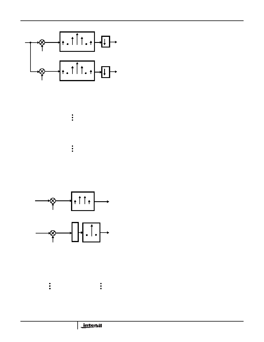
The HSP43216’s implementation of Down Convert and
Decimate mode is analogous to the polyphase solution
shown in Figure 14. The part’s data flow diagram for this
mode is shown in Figure 15A and Figure 15B. As seen in
the figures, the input sample data is broken into even and
odd sample streams which feed the upper and lower
processing legs as described in the Decimate By 2 Mode
section. The data on each processing leg is then
modulated with the nonzero quadrature components of the
complex exponent (see Quadrature Down Convert
Section). Following this operation, the upper leg becomes
the processing chain for the real (In-phase) component of
the quadrature down conversion and the lower leg
processes the complex (Quadrature) component of the
down conversion. The filter processing block implements
the equivalent of a decimate by two Halfband filter on each
of the quadrature legs.
If internal multiplexing is specified (INT/EXT = 1), the upper
and lower processing legs are fed with even and odd
sample streams which are derived from data input through
AIN0-15. The input sample stream may be synchronized
with the zero degree phase term of the down converter LO
by using the SYNC control input. For example, an input
data sample will be fed into the real (upper) processing leg
and mixed with the zero degree cosine term of the
quadrature LO if it is input on the 4th CLK following the
assertion of SYNC as shown in Figure 16. The pipeline
delay through the real processing leg (upper leg) is 14
CLK’s and the delay through the imaginary processing leg
(lower leg) is 47 CLK’s. The complex samples output
through AOUT0-15 and BOUT0-15 are present for 2 CLK’s
since the quadrature streams have been decimated by two
in the filter processor.
C0 C1 C2 C3 C4 C5 C6
...X2,X1,X0
...,R2,R0
2
C0 C1 C2 C3 C4 C5 C6
1, 0,-1, 0...
0,-1,0,1...
...,I2,I0
REAL OUTPUTS
R0 = X0(C0)+0(C1)-X2(C2)+0(C3)+X4(C4)+0(C5)-X6(C6)
R1 = 0(C0)-X2(C1)+0(C2)+X4(C3)+0(C4)-X6(C5)+0(C6)
R2 = -X2(C0)+0(C1)+X4(C2)+0(C3)-X6(C4)+0(C5)+X4(C6)
R3 = 0(C0)+X4(C1)+0(C2)-X6(C3)+0(C4)+X4(C5)+0(C6)
IMAGINARY OUTPUTS
I0 = 0(C0)-X1(C1)+0(C2)+X3(C3)+0(C4)-X5(C5)+0(C6)
I1 = -X1(C0)+0(C1)+X3(C2)+0(C3)-X5(C4)+0(C5)+X7(C6)
Indicates samples discarded by decimation process
I2 = 0(C0)+X3(C1)+0(C2)-X5(C3)+0(C4)+X7(C5)+0(C6)
I3 = X3(C0)+0(C1)-X5(C2)+0(C3)+X7(C4)+0(C5)-X9(C6)
HALFBAND FILTER
2
COS(
nπ/2)
SIN(-
nπ/2)
FIGURE 13. DOWN CONVERT AND DECIMATE FUNCTION
USING TRANSVERSAL FILTERS
C0 C2 C4 C6
...,X4,X2,X0
R0 = X0(C0)-X2(C2)+X4(C4)-X6(C6)
R1 = -X2(C0)+X4(C2)-X6(C4)+X8(C6)
C1 C3 C5
R
E
G
ODD TAP FILTER
EVEN TAP FILTER
R2 = X4(C0)-X6(C2)+X8(C4)-X10(C6)
1,-1,1,-1,..
-1,1,-1,1..
COS LO
SIN LO
...,X5,X3,X1
...,R1,R0
...,I1,I0
REAL OUTPUTS
I0 = -X1(C1)+X3(C3)-X5(C5)
I1 = X3(C1)-X5(C3)+X7(C5)
I2 = -X5(C1)+X7(C3)-X9(C5)
IMAGINARY OUTPUTS
FIGURE 14. DOWN CONVERT AND DECIMATE FUNCTION
USING POLYPHASE FILTERS
HSP43216
相關(guān)PDF資料 |
PDF描述 |
|---|---|
| HSP43220JC-33Z | IC DECIMATING DGTL FILTER 84PLCC |
| IA188EM-PTQ100I-R-03 | IC MCU 8/16BIT 40MHZ 100TQFP |
| IA188ES-PTQ100I-R-03 | IC MCU 8/16BIT 40MHZ 100TQFP |
| IA6805E2PLC44IR0 | IC MCU 8BIT 5MHZ 44PLCC |
| IA82050-PDW28I-R-01 | IC ASYNCHRONOUS SERIAL CTRL |
相關(guān)代理商/技術(shù)參數(shù) |
參數(shù)描述 |
|---|---|
| HSP43216JI-52 | 制造商:Rochester Electronics LLC 功能描述:- Bulk |
| HSP43216VC-52 | 功能描述:有源濾波器 HALFBAND FILTER 100 PIN PQFP,COMM RoHS:否 制造商:Maxim Integrated 通道數(shù)量:1 截止頻率:150 KHz 電源電壓-最大:11 V 電源電壓-最小:4.74 V 最大工作溫度:+ 85 C 安裝風(fēng)格:Through Hole 封裝 / 箱體:PDIP N 封裝:Tube |
| HSP43216VC-52Z | 功能描述:有源濾波器 W/ANNEAL HALFB & FILER 100 PIN PQFP RoHS:否 制造商:Maxim Integrated 通道數(shù)量:1 截止頻率:150 KHz 電源電壓-最大:11 V 電源電壓-最小:4.74 V 最大工作溫度:+ 85 C 安裝風(fēng)格:Through Hole 封裝 / 箱體:PDIP N 封裝:Tube |
| HSP43220 | 制造商:INTERSIL 制造商全稱:Intersil Corporation 功能描述:Decimating Digital Filter |
| HSP43220/883 | 制造商:INTERSIL 制造商全稱:Intersil Corporation 功能描述:Decimating Digital Filter |
發(fā)布緊急采購,3分鐘左右您將得到回復(fù)。