- 您現(xiàn)在的位置:買賣IC網(wǎng) > PDF目錄383055 > GS9001 (Electronic Theatre Controls, Inc.) EDH COPROCESSOR PDF資料下載
參數(shù)資料
| 型號: | GS9001 |
| 廠商: | Electronic Theatre Controls, Inc. |
| 英文描述: | EDH COPROCESSOR |
| 中文描述: | 硬腦膜外血腫協(xié)處理器 |
| 文件頁數(shù): | 9/14頁 |
| 文件大小: | 211K |
| 代理商: | GS9001 |

9
521 - 38 - 02
Word
Address
Databits
B4
Comments
B7
B6
B5
B3
B2
B1
B0
1
AP
IDH
AP
EDA
AP
EDH
ANC
UES
ANC
IDA
ANC
IDH
ANC
EDA
ANC
EDH
15 Error Flags (according to
SMPTE RPI65)
2
STICKY
FLAGS
FF
UES
FF
IDA
FF
IDH
FF
EDA
FF
EDH
AP
UES
AP
IDA
3
MAP
IDH
MAP
EDA
MAP
EDH
MANC
UES
MANC
IDA
MANC
IDH
MANC
EDA
MANC
EDH
Mask Status for the 15 Error
Flags (see Note 1)
4
MASK
RW
MFF
UES
MFF
IDA
MFF
IDH
MFF
EDA
MFF
EDH
MAP
UES
MAP
IDA
5
SAP
IDH
SAP
EDA
SAP
EDH
SALL
UES
SANC
IDA
SANC
IDH
SANC
EDA
SANC
EDH
Sensitivity Status for the15
Error Flags (see Note 2)
6
AUTO
CLR
CLR
CNT
TRS
SEL
SFF
IDA
SFF
IDH
SFF
EDA
SFF
EDH
SAP
IDA
7
RW1
b3
RW1
b2
0
0
SEL
STD
NTSC
PAL
HD1
D1
D1
D2
Standard Select (see Note 3)
8
RW2
b5
RW2
b4
RW2
b3
RW2
b2
RW1
b7
RW1
b6
RW1
b5
RW1
b4
Bits 2 to 7 for reserved words
1 to 7
Example: Bit number 4 of
reserved word 2 is
denoted as RW2 b4
9
RW3
b7
RW3
b6
RW3
b5
RW3
b4
RW3
b3
RW3
b2
RW2
b7
RW2
b6
10
RW5
b3
RW5
b2
RW4
b7
RW4
b6
RW4
b5
RW4
b4
RW4
b3
RW4
b2
11
RW6
b5
RW6
b4
RW6
b3
RW6
b2
RW5
b7
RW5
b6
RW5
b5
RW5
b4
12
RW7
b7
RW7
b6
RW7
b5
RW7
b4
RW7
b3
RW7
b2
RW6
b7
RW6
b6
NOTES:
1. Mask status is used for flag masking.
MASK RW is 1 to overwrite Reserved Words.
Bit STICKY FLAGS will make the flags sticky. (Flag stays set until read by
I
2
C interface)
2. Sensitivity status defines the interrupt & error counter sensitivity. Please note for UESflag sensitivity, there is only
one bit which is the SALL UESbit. This covers the UESbit for Ancillary, Active Picture and Full Field classes.
3. Bit SEL STD:
1 to overwrite video standard, 0 for auto standard selection
Bit NTSC/PAL: 1 for PAL (625/50) standard, 0 for NTSC (525/60) standard
Bit HD1/D1:
1 for Component 4:2:2 standard with 18Mhz Luminance, 0 for Component 4:2:2 standard
with 13.5 MHz Luminance
Bit D1/D2:
1 for 4
sc
composite standard, 0 for Component 4:2:2 standard
Bit TRS SEL:
1 to force TRS-ID indication in addition to ancillary data indication on the Ancillary Data pin, (pin 35)
0 to force only ancillary indication on the ancillary data pin (pin 35)
Bit CLR CNT:
1 to clear the ‘errored field counter’. 0 to let the counter count the errored fields
Bit AUTO CLR: 1 to automatically clear the ‘errored field counter’ after every reading of the counter status through the
interface, 0 to disable this automatic clear feature
Default Status: On power-up all bits are set to zero except for the sensitivity flags which are set to one.
Stand-Alone Operation:All bits will stay at power-up initial conditions, as described above, when there is no interface
connected to the device, except for the bit TRS-SEL, which can be set to one by connecting the
A1and A0 pins to 0,1 respectively.
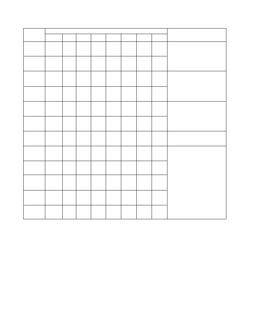
Table 5.
I
2
C - Interface: Data Format for WRITE 12 Words
相關PDF資料 |
PDF描述 |
|---|---|
| GS9001-CQM | EDH COPROCESSOR |
| GS9007ACKA | Quad Serial Digital Cable Driver |
| GS9007ACKAE3 | JT 26C 26#20 SKT PLUG |
| GS9007A | Quad Serial Digital Cable Driver |
| GS9008 | Cable Driver with Two Adjustable Outputs |
相關代理商/技術參數(shù) |
參數(shù)描述 |
|---|---|
| GS9001_04 | 制造商:GENNUM 制造商全稱:GENNUM 功能描述:EDH Coprocessor |
| GS90015BCPJE3 | 制造商:GENNUM 制造商全稱:GENNUM 功能描述:GENLINX-TM GS9015B Serial Digital Reclocker |
| GS9001-CQM | 制造商:Rochester Electronics LLC 功能描述: 制造商:Gennum Corporation 功能描述: |
| GS9001-CQME3 | 制造商:Semtech Corporation 功能描述:EDH Co-Processer |
| GS9001-CTM | 制造商:Rochester Electronics LLC 功能描述: 制造商:Gennum Corporation 功能描述: |
發(fā)布緊急采購,3分鐘左右您將得到回復。