- 您現(xiàn)在的位置:買賣IC網(wǎng) > PDF目錄370378 > GS-D200S (意法半導(dǎo)體) 2/2.5A Bipolar Stepper Motor Driver Modules(2/2.5A雙極型步進(jìn)電機(jī)驅(qū)動(dòng)器模塊) PDF資料下載
參數(shù)資料
| 型號(hào): | GS-D200S |
| 廠商: | 意法半導(dǎo)體 |
| 英文描述: | 2/2.5A Bipolar Stepper Motor Driver Modules(2/2.5A雙極型步進(jìn)電機(jī)驅(qū)動(dòng)器模塊) |
| 中文描述: | 2/2.5A雙極步進(jìn)電機(jī)驅(qū)動(dòng)器模塊(2/2.5A雙極型步進(jìn)電機(jī)驅(qū)動(dòng)器模塊) |
| 文件頁(yè)數(shù): | 14/17頁(yè) |
| 文件大小: | 183K |
| 代理商: | GS-D200S |
第1頁(yè)第2頁(yè)第3頁(yè)第4頁(yè)第5頁(yè)第6頁(yè)第7頁(yè)第8頁(yè)第9頁(yè)第10頁(yè)第11頁(yè)第12頁(yè)第13頁(yè)當(dāng)前第14頁(yè)第15頁(yè)第16頁(yè)第17頁(yè)
14/17
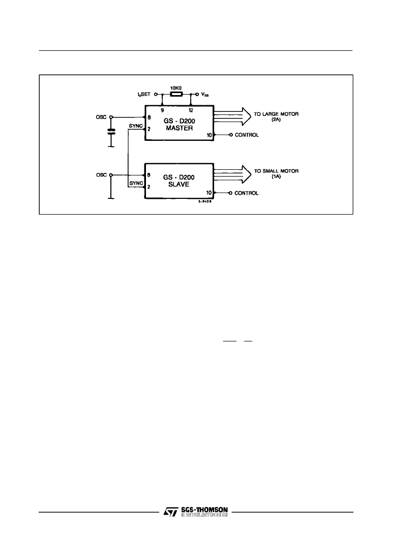
Figure 19:Multimotor Synchronization. Large and Small Motor. Slow Current Decay
THERMAL OPERATING CONDITIONS
In many cases the modules do not require any
additional cooling because the dimensions and the
shape of the metal box are studied to offer the
minimum possible thermal resistance case-to-am-
bient for a given volume.
It should be remembered that these modules are a
power device and, depending onambient tempera-
ture, an additional heath-sink or forced ventilation
or both may berequiredto keep the unit within safe
temperature range. (Tcase
max
< 85
°
C during op-
eration).
The concept of maximum operating ambient tem-
perature is totally meaningless when dealing with
power components becausethe maximum operat-
ing ambienttemperature dependson howa power
device is used.
What can be unambiguously defined is the case
temperature of the module.
To calculate the maximum case temperature of the
module in a particular applicative environment the
designer must know the following data:
– Input voltage
– Motor phase current
– Motor phase resistance
– Maximum ambient temperature
From thesedata itis easy to determine whether an
additional heath-sink is required or not, and the
relevant size i.e. the thermal resistance.
The stepby step calculation isshown for the follow-
ing example (GS-D200).
V
in
= 40 V, I
phase
= 1 A, R
ph
Phase resistance =
=10
, max. T
A
= 50
°
C
G
Calculate the power dissipated from the indexer
logic and the level shifter (see electrical charac-
teristics):
P
logic
= (5 V
60 mA) + (40 V
20 mA) = 1.1 W
G
Calculatetheaverage voltageacrossthe winding
resistance:
V
out
= (R
ph
I
out
) = 10
ζ
1 A= 10 V
G
Calculate the required ONdutycycle (D.C.) ofthe
output stage to obtain the average voltage (this
D.C. is automaticallyadjusted by the GS-D200):
D.C.
=
V
out
V
in
G
Calculate the power dissipation of the GS-D200
output power stage. The power dissipation de-
pends on two main factors:
– the selected operating mode (FAST or SLOW
DECAY)
– the selected drive sequence (WAVE, NORMAL,
HALF STEP)
FAST DECAY. For this mode of operation, the
internal voltage drop isVsat
source
+Vsat
sink
during
the ON period i.e. for 25 % of the time.
During the recirculation period (75 % of the time),
the current recirculates on two internal diodes that
have avoltage dropV
d
=1 V, andthe internal sense
resistor (0.5
). For this example, by assuming
maximum values for conservative calculations, the
power dissipation during one cycle is:
P
pw
= 1.1
[2 V
sat
I
ph
D.C. + 2 V
d
I
ph
(1 - D.C.) + 0.5
I
ph
]
=
10
40
=
0.25
GS-D200/GS-D200S
相關(guān)PDF資料 |
PDF描述 |
|---|---|
| GS-D500A | 100V/5A STEP AND MICROSTEP DRIVE BOARD FOR STEPPER MOTORS |
| GS-DC200 | STEPPER MOTOR CONTROL AND DRIVE SYSTEM FAMILY |
| GS-DC200S | STEPPER MOTOR CONTROL AND DRIVE SYSTEM FAMILY |
| GS-DC200SS | STEPPER MOTOR CONTROL AND DRIVE SYSTEM FAMILY |
| GS-F8MB-SIMM | 8MByte SIMM Flash Memory Module(8M字節(jié)SIMM閃速存儲(chǔ)器模塊) |
相關(guān)代理商/技術(shù)參數(shù) |
參數(shù)描述 |
|---|---|
| GSD-250 | 功能描述:自耦變壓器 230Vin 115Vout 50/60Hz 2.2A 250VA RoHS:否 制造商:Hammond Manufacturing 功率額定值:1.5 KVA 初級(jí)電壓額定值: 次級(jí)電壓額定值: 安裝風(fēng)格: 長(zhǎng)度: 寬度:111.76 mm 高度:136.91 mm |
| GSD2656 | 制造商:GTM 制造商全稱:GTM 功能描述:NPN EPITAXIAL TRANSISTOR |
| GSD-300 | 制造商:Stancor 功能描述:Power Transformer 1500Vrms 230V Prim. 115V Sec. Flange Mount |
| GSD304020GP2 | 制造商:Pentair Technical Products / Hoffman 功能描述:GLOBAL WALL-MOUNT ENCLOSURE, GLAND P 制造商:PENTAIR TECNICAL PRODCUTS 功能描述:GLOBAL WALL-MOUNT ENCLOSURE, GLAND P |
| GSD-329 | 制造商:Duratool 功能描述:All-in-One Screwdriver and Bit Set with Wire Stripper |
發(fā)布緊急采購(gòu),3分鐘左右您將得到回復(fù)。