- 您現(xiàn)在的位置:買賣IC網(wǎng) > PDF目錄67593 > FW330G71-56T 1-OUTPUT 250 W DC-DC REG PWR SUPPLY MODULE PDF資料下載
參數(shù)資料
| 型號(hào): | FW330G71-56T |
| 元件分類: | 電源模塊 |
| 英文描述: | 1-OUTPUT 250 W DC-DC REG PWR SUPPLY MODULE |
| 封裝: | 2.40 X 4.60 INCH, 0.57 INCH HEIGHT, POWER MODULE |
| 文件頁數(shù): | 10/29頁 |
| 文件大小: | 347K |
| 代理商: | FW330G71-56T |
第1頁第2頁第3頁第4頁第5頁第6頁第7頁第8頁第9頁當(dāng)前第10頁第11頁第12頁第13頁第14頁第15頁第16頁第17頁第18頁第19頁第20頁第21頁第22頁第23頁第24頁第25頁第26頁第27頁第28頁第29頁
Tyco Electronics Corp.
17
Advance Data Sheet
March 2000
36 to 75 Vdc Input, 3.6, 3.3, 2.5, 2.0, or 1.8 Vdc Output; 180 W to 330 W
FW330 Power Modules: dc-dc Converters;
Feature Descriptions (continued)
Power Good Signal (continued)
The output undervoltage set-point is adjustable by
using the output undervoltage set-point adjustment pin
(OUSPadj). This is accomplished by connecting an
external resistor between the OUSPadj pin and the
SENSE(–) pin (see Figure 27). The following equation
determines the required external-resistor value to
obtain a percentage output voltage set-point of
%.
For 1.8 V:
For 2.0 V:
For 2.5 V:
For 3.3 V:
For 3.6 V:
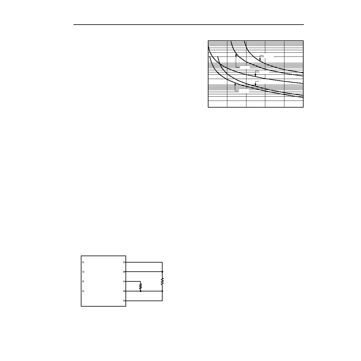
The test results for this conguration are displayed in
Figure 28. This gure applies to all output voltages.
If not using the output undervoltage set-point adjust
feature, leave the OUSPadj pin open. When the
OUSPadj pin is left open, the set-point of the output
undervoltage is about half of the nominal output volt-
age.
8-2898 (C)
Figure 27. Circuit Conguration to Adjust the
Output Undervoltage Set-Point
8-3067 (F)
Figure 28. Resistor Selection for Output
Undervoltage Set-Point Adjustment
There is one situation where the power good signal can
be low even though the module has failed. This can
occur when the module is paralleled with other mod-
ules for additional output power (i.e., the output ORing
diodes would not be used). If one module power train
stops delivering power (fails), the other paralleled mod-
ule(s) would provide a voltage at the output pin of the
failed module. The failed module would then not detect
that its output power was not being delivered. However,
in this situation, the current monitor pins of the paral-
leled modules would indicate that current is not being
delivered from one module and that module had failed.
For redundant applications, the ORing diodes would
keep the other module voltages from being applied to
the failed module output and the power good signal
would indicate a failure.
Radj
1218
%
–
% – 68
-------------------------------
k
=
Radj
1096
%
–
% – 61.25
-------------------------------
k
=
Radj
701
%
–
% – 49
----------------------------
k
=
Radj
256
%
–
% – 54
----------------------------
k
=
Radj
241
%
–
% – 50
----------------------------
k
=
VI(+)
VI(–)
ON/OFF
CASE
VO(+)
VO(–)
SENSE(+)
OUSPadj
SENSE(–)
Radj
RLOAD
50
% CHANGE IN OUTPUT VOLTAGE (
%)
ADJUSTMENT
RESISTOR
VALUE
(
)
1k
60
70
80
90
100k
10k
100
1M
3.3 V
3.6 V
2.5 V
2.0 V
1.8 V
相關(guān)PDF資料 |
PDF描述 |
|---|---|
| FW330S3R671-56 | 1-OUTPUT 330 W DC-DC REG PWR SUPPLY MODULE |
| FW330F1-33T | 1-OUTPUT 330 W DC-DC REG PWR SUPPLY MODULE |
| FW330Y1-33T | 1-OUTPUT 180 W DC-DC REG PWR SUPPLY MODULE |
| FW400R61-18 | 1-OUTPUT 392 W DC-DC REG PWR SUPPLY MODULE |
| FX2030C | SPECIALTY CONSUMER CIRCUIT, DIP42 |
相關(guān)代理商/技術(shù)參數(shù) |
參數(shù)描述 |
|---|---|
| FW332 | 制造商:未知廠家 制造商全稱:未知廠家 功能描述: |
| FW340 | 制造商:SANYO 制造商全稱:Sanyo Semicon Device 功能描述:N-Channel and P-Channel Silicon MOSFETs General-Purpose Switching Device |
| FW-34-01-F-D-250-100 | 制造商:Samtec Inc 功能描述:.050'' BOARD SPACERS - Bulk |
| FW-34-01-F-D-280-125 | 制造商:Samtec Inc 功能描述:.050'' BOARD SPACERS - Bulk |
| FW-34-01-F-D-350-065 | 制造商:Samtec Inc 功能描述:CONN BD STACKER HDR 68 POS 1.27MM SLDR ST TH - Bulk |
發(fā)布緊急采購(gòu),3分鐘左右您將得到回復(fù)。