- 您現(xiàn)在的位置:買賣IC網(wǎng) > PDF目錄67593 > FW330F1 1-OUTPUT 330 W DC-DC REG PWR SUPPLY MODULE PDF資料下載
參數(shù)資料
| 型號(hào): | FW330F1 |
| 元件分類: | 電源模塊 |
| 英文描述: | 1-OUTPUT 330 W DC-DC REG PWR SUPPLY MODULE |
| 封裝: | 2.40 X 4.60 INCH, 0.57 INCH HEIGHT, POWER MODULE |
| 文件頁(yè)數(shù): | 6/29頁(yè) |
| 文件大小: | 347K |
| 代理商: | FW330F1 |
第1頁(yè)第2頁(yè)第3頁(yè)第4頁(yè)第5頁(yè)當(dāng)前第6頁(yè)第7頁(yè)第8頁(yè)第9頁(yè)第10頁(yè)第11頁(yè)第12頁(yè)第13頁(yè)第14頁(yè)第15頁(yè)第16頁(yè)第17頁(yè)第18頁(yè)第19頁(yè)第20頁(yè)第21頁(yè)第22頁(yè)第23頁(yè)第24頁(yè)第25頁(yè)第26頁(yè)第27頁(yè)第28頁(yè)第29頁(yè)
Tyco Electronics Corp.
13
Advance Data Sheet
March 2000
36 to 75 Vdc Input, 3.6, 3.3, 2.5, 2.0, or 1.8 Vdc Output; 180 W to 330 W
FW330 Power Modules: dc-dc Converters;
Feature Descriptions (continued)
Remote Sense
Remote sense minimizes the effects of distribution
losses by regulating the voltage at the remote-sense
connections. The voltage between the remote-sense
pins and the output terminals must not exceed the out-
put voltage sense range given in the Feature Specica-
tions table, i.e.:
[VO(+) – VO(–)] – [SENSE(+) – SENSE(–)]
≤ 0.5 V
The voltage between the VO(+) and VO(–) terminals
must not exceed the minimum value indicated in the
output overvoltage shutdown section of the Feature
Specications table. This limit includes any increase in
voltage due to remote-sense compensation and output
voltage set-point adjustment (trim), see Figure 21.
For remote-sense operation with multiple paralleled
units, see the Forced Load Sharing (Parallel Opera-
tion) section.
Note: The output voltage of this module may be
increased to a maximum of 0.5 V. The 0.5 V is
the combination of both the remote sense and
the output voltage set-point adjustment (trim).
If not using the remote-sense feature to regulate the out-
put at the point of load, connect SENSE(+) to VO(+) and
SENSE(–) to VO(–) at the module.
Although the output voltage can be increased by both
the remote sense and by the trim, the maximum
increase for the output voltage is not the sum of both.
The maximum increase is the larger of either the
remote sense or the trim. Consult the factory if you
need to increase the output voltage more than the
above limitation.
The amount of power delivered by the module is
dened as the voltage at the output terminals multiplied
by the output current. When using remote sense and
trim, the output voltage of the module can be
increased, which at the same output current would
increase the power output of the module. Care should
be taken to ensure that the maximum output power of
the module remains at or below the maximum rated
power.
8-651 (C).e
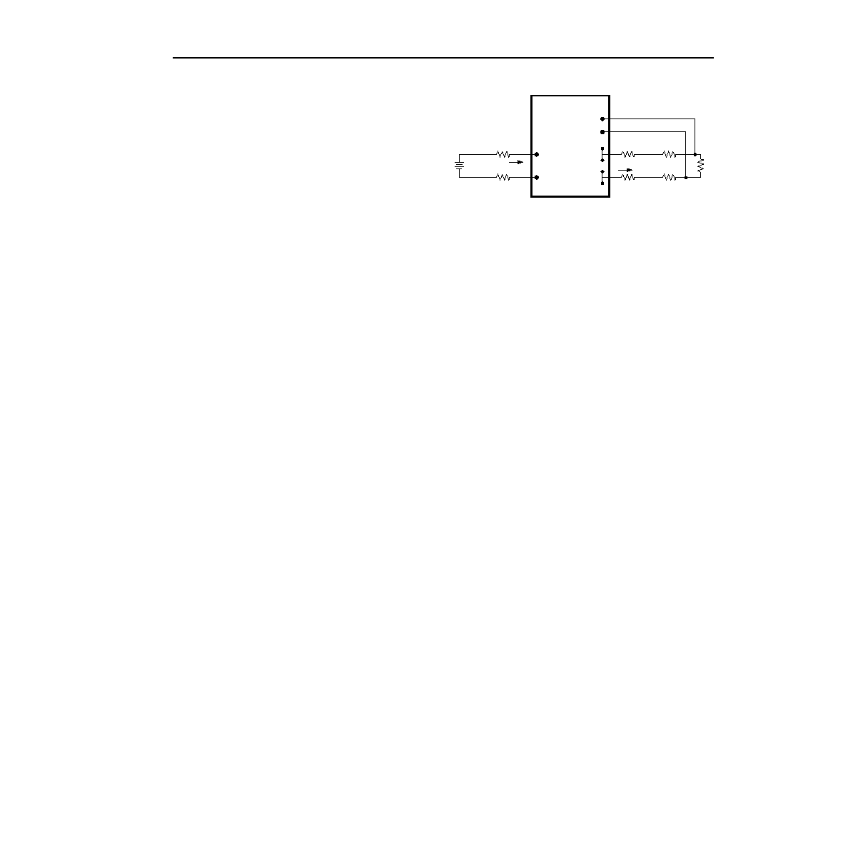
Figure 21. Effective Circuit Conguration for
Single-Module Remote-Sense Operation
Output Voltage Set-Point Adjustment (Trim)
Output voltage trim allows the user to increase or
decrease the output voltage set point of a module. This
is accomplished by connecting an external resistor
between the TRIM pin and either the SENSE(+) or
SENSE(–) pins. The trim resistor should be positioned
close to the module.
If not using the trim feature, leave the TRIM pin open.
With an external resistor between the TRIM and
SENSE(–) pins (Radj-down), the output voltage set point
tion determines the required external-resistor value to
obtain a percentage output voltage change of
%.
The test results for this conguration are displayed in
Figure 23. This gure applies to all output voltages.
With an external resistor connected between the TRIM
and SENSE(+) pins (Radj-up), the output voltage set
The following equation determines the required exter-
nal-resistor value to obtain a percentage output voltage
change of
%.
The test results for this conguration are displayed in
Figure 25.
Note: The output voltage of this module may be
increased to a maximum of 0.5 V. The 0.5 V is
the combination of both the remote sense and
the output voltage set-point adjustment (trim).
VO(+)
SENSE(+)
SENSE(–)
VO(–)
VI(+)
VI(–)
IO
LOAD
CONTACT AND
DISTRIBUTION LOSSES
SUPPLY
II
CONTACT
RESISTANCE
Radj-down
205
%
----------
2.255
–
k
=
Radj-up
VO, nom 1
%
100
----------
+
() 1.225
–
()
1.225
%
()
------------------------------------------------------------------------- 205
2.255
–
k
=
相關(guān)PDF資料 |
PDF描述 |
|---|---|
| FW330G71-56T | 1-OUTPUT 250 W DC-DC REG PWR SUPPLY MODULE |
| FW330S3R671-56 | 1-OUTPUT 330 W DC-DC REG PWR SUPPLY MODULE |
| FW330F1-33T | 1-OUTPUT 330 W DC-DC REG PWR SUPPLY MODULE |
| FW330Y1-33T | 1-OUTPUT 180 W DC-DC REG PWR SUPPLY MODULE |
| FW400R61-18 | 1-OUTPUT 392 W DC-DC REG PWR SUPPLY MODULE |
相關(guān)代理商/技術(shù)參數(shù) |
參數(shù)描述 |
|---|---|
| FW330F1-59T | 制造商:GE Energy (formerly Lineage Power) 功能描述:108755794 |
| FW330G71-56T | 制造商:GE Energy (formerly Lineage Power) 功能描述:Module DC-DC 1-OUT 2.5V 100A 330W 22-Pin |
| FW332 | 制造商:未知廠家 制造商全稱:未知廠家 功能描述: |
| FW340 | 制造商:SANYO 制造商全稱:Sanyo Semicon Device 功能描述:N-Channel and P-Channel Silicon MOSFETs General-Purpose Switching Device |
| FW-34-01-F-D-250-100 | 制造商:Samtec Inc 功能描述:.050'' BOARD SPACERS - Bulk |
發(fā)布緊急采購(gòu),3分鐘左右您將得到回復(fù)。