- 您現(xiàn)在的位置:買賣IC網(wǎng) > PDF目錄67504 > FM3204-G SPECIALTY CONSUMER CIRCUIT, PDSO14 PDF資料下載
參數(shù)資料
| 型號: | FM3204-G |
| 元件分類: | 消費家電 |
| 英文描述: | SPECIALTY CONSUMER CIRCUIT, PDSO14 |
| 封裝: | GREEN, MS-012AB, SOIC-14 |
| 文件頁數(shù): | 18/21頁 |
| 文件大?。?/td> | 424K |
| 代理商: | FM3204-G |
FM3204/16/64/256
Rev. 3.1
July 2010
Page 6 of 21
The voltage on the PFI input pin is compared to an
onboard 1.2V reference. When the PFI input voltage
drops below this threshold, the comparator will drive
the PFO pin to a low state. The comparator has 100
mV (max) of hysteresis to reduce noise sensitivity,
only for a rising PFI signal. For a falling PFI edge,
there is no hysteresis.
The comparator is a general purpose device and its
application is not limited to the NMI function.
Note: The maximum voltage on the comparator input
PFI is limited to 3.75V under normal operating
conditions.
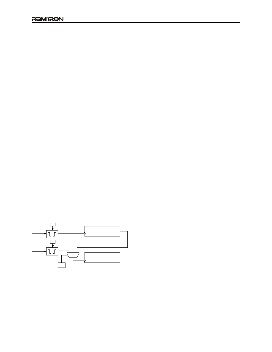
Event Counter
The FM32xx offers the user two battery-backed event
counters. Input pins CNT1 and CNT2 are
programmable edge detectors. Each clocks a 16-bit
counter. When an edge occurs, the counters will
increment their respective registers. Counter 1 is
located in registers 0Dh and 0Eh, Counter 2 is
located in registers 0Fh and 10h. These register
values can be read anytime VDD is above VTP, and
they will be incremented as long as a valid VBAK
power source is provided. To read, set the RC bit
register 0Ch bit 3 to 1. This takes a snapshot of all
four counter bytes allowing a stable value even if a
count occurs during the read. The registers can be
written by software allowing the counters to be
cleared or initialized by the system. Counts are
blocked during a write operation. The two counters
can be cascaded to create a single 32-bit counter by
setting the CC control bit (register 0Ch). When
cascaded, the CNT1 input will cause the counter to
increment. CNT2 is not used in this mode.
Figure 6. Event Counter
The control bits for event counting are located in
register 0Ch. Counter 1 Polarity is bit C1P, bit 0;
Counter 2 Polarity is C2P, bit 1; the Cascade Control
is CC, bit 2; and the Read Counter bit is RC bit 3.
The polarity bits must be set prior to setting the
counter value(s). If a polarity bit is changed, the
counter may inadvertently increment. If the counter
pins are not being used, tie them to ground.
Serial Number
A memory location to write a 64-bit serial number is
provided. It is a writeable nonvolatile memory block
that can be locked by the user once the serial number
is set. The 8 bytes of data and the lock bit are all
accessed via the device ID for the processor
companion. Therefore the serial number area is
separate and distinct from the memory array. The
serial number registers can be written an unlimited
number of times, so these locations are general
purpose memory. However once the lock bit is set the
values cannot be altered and the lock cannot be
removed. Once locked the serial number registers can
still be read by the system.
The serial number is located in registers 11h to 18h.
The lock bit is SNL, register 0Bh bit 7. Setting the
SNL bit to a 1 disables writes to the serial number
registers, and the SNL bit cannot be cleared.
Backup Power
The event counter and battery-backed registers may
be powered with a backup power source. When the
primary system power fails, the voltage on the VDD
pin will drop. When VDD is less than 2.5V, the event
counters and battery-backed registers will switch to
the backup power supply on VBAK.
Trickle Charger
To facilitate capacitor backup the VBAK pin can
optionally provide a trickle charge current. When the
VBC bit, register 0Bh bit 2, is set to 1 the VBAK pin
will source approximately 15 A until VBAK reaches
VDD or 3.75V whichever is less. In 3V systems, this
charges the capacitor to VDD without an external
diode and resistor charger. In 5V systems, it provides
the same convenience and also prevents the user from
exceeding the VBAK maximum voltage specification.
In the case where no battery is used, the VBAK pin
should be tied according to the following conditions:
For 3.3V systems, VBAK should be tied to VDD.
This assumes VDD does not exceed 3.75V.
For 5V systems, attach a 1 F capacitor to VBAK
and turn the trickle charger on. The VBAK pin
will charge to the internal backup voltage which
regulates itself to about 3.6V. VBAK should not
be tied to 5V since the VBAK (max) specification
will be exceeded. A 1 F capacitor will keep
the companion functions working for about 1.5
second.
16-bit Counter
CNT1
CC
CNT2
C1P
C2P
16-bit Counter
相關PDF資料 |
PDF描述 |
|---|---|
| FM3216-G | SPECIALTY CONSUMER CIRCUIT, PDSO14 |
| FM3264-G | SPECIALTY CONSUMER CIRCUIT, PDSO14 |
| FM32272-GTR | SPECIALTY CONSUMER CIRCUIT, PDSO14 |
| FM32272-G | SPECIALTY CONSUMER CIRCUIT, PDSO14 |
| FM32274-GTR | SPECIALTY CONSUMER CIRCUIT, PDSO14 |
相關代理商/技術參數(shù) |
參數(shù)描述 |
|---|---|
| FM3204-GTR | 功能描述:監(jiān)控電路 4K w/Pwr Mon WDT Bat Sw Pwr Fail RoHS:否 制造商:STMicroelectronics 監(jiān)測電壓數(shù): 監(jiān)測電壓: 欠電壓閾值: 過電壓閾值: 輸出類型:Active Low, Open Drain 人工復位:Resettable 監(jiān)視器:No Watchdog 電池備用開關:No Backup 上電復位延遲(典型值):10 s 電源電壓-最大:5.5 V 最大工作溫度:+ 85 C 安裝風格:SMD/SMT 封裝 / 箱體:UDFN-6 封裝:Reel |
| FM3204-S | 功能描述:監(jiān)控電路 4K w/Pwr Mon WDT Bat Sw Pwr Fail RoHS:否 制造商:STMicroelectronics 監(jiān)測電壓數(shù): 監(jiān)測電壓: 欠電壓閾值: 過電壓閾值: 輸出類型:Active Low, Open Drain 人工復位:Resettable 監(jiān)視器:No Watchdog 電池備用開關:No Backup 上電復位延遲(典型值):10 s 電源電壓-最大:5.5 V 最大工作溫度:+ 85 C 安裝風格:SMD/SMT 封裝 / 箱體:UDFN-6 封裝:Reel |
| FM3204-STR | 功能描述:監(jiān)控電路 4K w/Pwr Mon WDT Bat Sw Pwr Fail RoHS:否 制造商:STMicroelectronics 監(jiān)測電壓數(shù): 監(jiān)測電壓: 欠電壓閾值: 過電壓閾值: 輸出類型:Active Low, Open Drain 人工復位:Resettable 監(jiān)視器:No Watchdog 電池備用開關:No Backup 上電復位延遲(典型值):10 s 電源電壓-最大:5.5 V 最大工作溫度:+ 85 C 安裝風格:SMD/SMT 封裝 / 箱體:UDFN-6 封裝:Reel |
| FM320A | 制造商:RECTRON 制造商全稱:Rectron Semiconductor 功能描述:SURFACE MOUNT SCHOTTKY BARRIER RECTIFIER VOLTAGE RANGE 20 to 60 Volts CURRENT 3.0 Amperes |
| FM320-A | 制造商:FORMOSA 制造商全稱:Formosa MS 功能描述:Chip Schottky Barrier Diodes - Silicon epitaxial planer type |
發(fā)布緊急采購,3分鐘左右您將得到回復。