- 您現(xiàn)在的位置:買賣IC網(wǎng) > PDF目錄223792 > FLIP Flip Chip TVS Evaluation and Assembly Guide (101k) PDF資料下載
參數(shù)資料
| 型號(hào): | FLIP |
| 英文描述: | Flip Chip TVS Evaluation and Assembly Guide (101k) |
| 中文描述: | 倒裝芯片二極管評(píng)價(jià)和大會(huì)指南(101k) |
| 文件頁數(shù): | 1/3頁 |
| 文件大小: | 101K |
| 代理商: | FLIP |

PROTECTION PRODUCTS
1
www.semtech.com
PROTECTION PRODUCTS
SI00-06
Surging Ideas
TVS Diode Application Note
Revision 11/2001
Flip Chip TVS Evaluation and Assembly Guide
Introduction
The Semtech flip chip TVS is a state-of-the-art
component designed to meet the protection needs of
today’s portable electronic devices. The advantages of
flip chip technology include reduced size and weight,
improved electrical performance, and low profile.
These devices are designed to be compatible with
standard surface mount technology (SMT) assembly
processes. This document will explain a few assembly
and layout guidelines needed to successfully
implement Semtech’s flip chip TVS components.
Description
There is often confusion as to the classification of
devices as flip chip or chip scale packages (CSP).
There is no precise definition for either. CSP
configurations are often broadly classified by solder
bump height or by package sizes. The latter definition
is a device with a package size that is 1.2 to 1.5 times
the size of the die. Devices that are smaller then 1.2
times the die area are often referred to as flip chip.
Additionally, CSP devices are sometimes defined as
requiring an interposer (such as a film or laminate
layer) between the silicon IC and the PCB for purposes
of redistributing the device connections. However, this
is not always true. Many CSP devices do not require
an interposer layer. Additionally, some literature
defines CSP devices as being compatible with current
surface mount assembly technologies, while flip chip
devices are not. Semtech’s devices have a package to
die size ratio of 1:1 and do not require an interposer
layer. They are also compatible with current high
volume assembly technology. Therefore, Semtech’s
devices could be classified as either flip chip or CSP
components.
Package Construction
The flip chip TVS consists of a silicon IC with a
proprietary surface passivation and solder balls or
bumps on the active side of the device. The solder
bump structure is a key component to the long-term
reliability and assembly considerations of the device.
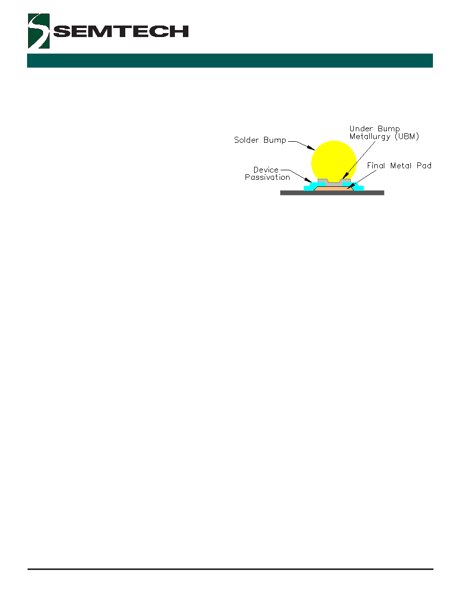
The solder bump is actually a metallurgical system
consisting of a metal pad, under bump metal (UBM),
and a solder ball. There are several technologies for
applying solder bumps to flip chip components.
Semtech utilizes a proprietary electroless nickel plate
process for the UBM paired with screen printed solder
balls. The balls are laid out in a grid with a pin out
pattern per JEDEC standard outline MO-211.
Figure 1 - Anatomy of a Solder Bump
Assembly Processes and Design Optimization
The reliability performance of the solder balls after the
device is attached to the board is a strong function of
the board design and assembly parameters. Although
a flip chip wafer level device is designed to be
compatible with standard surface mount technology
assembly process, certain precautions and design
considerations must be in place to assemble these
devices for maximum reliability.
Board Design
The first consideration the designer is faced with is pad
size and definition. Figure 2 shows the recommended
printed circuit board (PCB) footprint for the 3 x 2 grid
array (1 x 1.5 0.7mm) flip chip TVS. The solder pads
are circular with a diameter of 0.225 ± 0.010mm. This
size was chosen because it is the minimum diameter
that can be consistently achieved by most PCB
manufacturers. Ideally, the pad size would not deviate
more than +/- 0.010mm from the nominal diameter of
the solder balls.
Theoretically, SMD (solder mask defined) pads should
provide increased thermal cycling reliability over NSMD
(non-solder mask defined) pads due to higher stand off
of SMD solder balls. However, this is not the case.
The mask on SMD will touch solder ball after reflow
potentially introducing a stress concentration point
near the solder mask/ball interface. This can cause
cracks in the solder ball leading to premature solder
joint failure during extreme fatigue conditions (such as
temperature cycle) for an SMD pad design. By leaving
the gap in the solder mask (NSMD), the stress at the
相關(guān)PDF資料 |
PDF描述 |
|---|---|
| FLJ-ACO1 | Consumer IC |
| FLJ-ACR1 | Digital Potentiometer |
| FLJ-ACR2 | Digital Potentiometer |
| FLJ-D1 | Analog Filter |
| FLJ-D2 | Analog Filter |
相關(guān)代理商/技術(shù)參數(shù) |
參數(shù)描述 |
|---|---|
| FLIPCHIP11 | 制造商:STMICROELECTRONICS 制造商全稱:STMicroelectronics 功能描述:4-BIT DUAL SUPPLY BUS BUFFER LEVEL TRANSLATOR WITH A SIDE SERIES RESISTOR |
| FLIR A15SC | 制造商:FLIR COMMERCIAL SYSTEMS 功能描述:FLIR A15 Imager (160 x 128)/f = 9 mm (48 deg x 39 deg) Lens with Science Kit |
| FLIR A5SC | 制造商:FLIR COMMERCIAL SYSTEMS 功能描述:FLIR A5 Imager (80 x 64)/f = 5 mm (44 deg x 36 deg) Lens with Science Kit |
| FLIR B200 | 功能描述:熱成像器 BldgTher Imag IR Cam 200x150 Res/9Hz RoHS:否 制造商:Fluke 溫度范圍:- 20 C to + 600 C 分辨率:280 X 210 靈敏度:0.05 C 準(zhǔn)確性:2 % 顯示器類型:LCD |
| FLIR B300 | 功能描述:熱成像器 BldgTher Imag IR Cam 320x240 Res/2X RoHS:否 制造商:Fluke 溫度范圍:- 20 C to + 600 C 分辨率:280 X 210 靈敏度:0.05 C 準(zhǔn)確性:2 % 顯示器類型:LCD |
發(fā)布緊急采購,3分鐘左右您將得到回復(fù)。