- 您現(xiàn)在的位置:買賣IC網 > PDF目錄370152 > FB2041 (NXP Semiconductors N.V.) 7-bit Futurebus+ transceiver(7位預置總線收發(fā)器) PDF資料下載
參數(shù)資料
| 型號: | FB2041 |
| 廠商: | NXP Semiconductors N.V. |
| 英文描述: | 7-bit Futurebus+ transceiver(7位預置總線收發(fā)器) |
| 中文描述: | 7位Futurebus收發(fā)器(7位預置總線收發(fā)器) |
| 文件頁數(shù): | 8/14頁 |
| 文件大小: | 148K |
| 代理商: | FB2041 |

Philips Semiconductors
Product specification
FB2041
7-bit Futurebus+ transceiver
1995 May 25
8
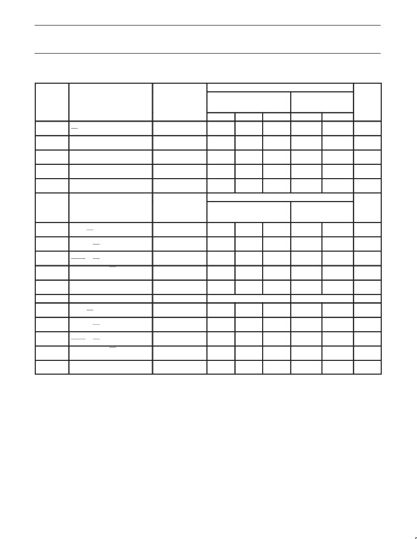
AC ELECTRICAL CHARACTERISTICS
(Commercial)
A PORT LIMITS
SYMBOL
PARAMETER
TEST
CONDITION
T
amb
= +25
°
C, V
= 5V,
L
= 50pF, R
L
= 500
MIN
TYP
1.8
1.6
3.2
2.2
2.0
4.0
1.5
1.8
3.0
1.5
1.5
2.4
T
amb
= 0 to 70
°
C,
V
= 5V
±
10%,
C
L
= 50pF, R
L
= 500
MIN
1.6
1.6
2.0
1.8
1.2
1.5
1.5
1.5
UNIT
MAX
5.0
4.9
6.5
6.5
4.8
5.0
3.0
3.0
MAX
5.5
5.0
10.0
8.0
5.0
5.5
3.5
3.5
t
PLH
t
PHL
t
PZH
t
PZL
t
PHZ
t
PLZ
t
TLH
t
THL
Propagation delay,
Bn to AOn
Output enable time,
OEA to AOn
Output disable time,
OEA to AOn
Transition time, AOn Port
(10% to 90% or 90% to 10%)
Output skew between receivers
in same package
1
Waveform 1, 2
3.4
ns
Waveform 4, 5
5.0
ns
Waveform 4, 5
3.3
ns
Test Circuit and
Waveforms
2.2
ns
t
SK
(o)
Waveform 3
0.4
1.0
1.0
ns
B PORT LIMITS
SYMBOL
PARAMETER
TEST CONDITION
T
amb
= +25
°
C, V
CC
= 5V,
D
= 30pF, R
U
T
amb
= 0 to 70
°
C,
V
= 5V
±
10%,
C
D
= 30pF, R
U
= 9
1.9
1.5
1.9
1.8
1.9
2.5
1.0
0.5
UNIT
t
PLH
t
PHL
t
PLH
t
PHL
t
PLH
t
PHL
t
TLH
t
THL
Propagation delay,
AIn to Bn
Enable/disable time,
OEB0 to Bn
Enable/disable time,
OEB1 to Bn
Transition time, Bn Port
(1.3V to 1.8V)
Output skew between drivers in
same package
1
PARAMETER
Propagation delay,
AIn to Bn
Enable/disable time,
OEB0 to Bn
Enable/disable time,
OEB1 to Bn
Transition time, Bn Port
(1.3V to 1.8V)
Output skew between drivers in
same package
1
Waveform 1, 2
2.4
1.5
2.4
1.9
2.4
1.9
1.0
0.5
3.7
2.7
3.7
3.5
4.0
3.6
1.4
1.1
4.9
4.4
4.9
4.9
5.5
5.5
3.0
3.0
5.7
5.0
6.4
5.4
5.9
5.9
3.0
3.0
ns
Waveform 2
ns
Waveform 1
ns
Test Circuit and
Waveforms
ns
t
SK
(o)
Waveform 3
0.3
1.0
1.0
ns
SYMBOL
t
PLH
t
PHL
t
PLH
t
PHL
t
PLH
t
PHL
t
TLH
t
THL
TEST CONDITION
R
U
= 16.5
3.8
2.8
3.8
3.6
4.1
3.7
1.5
1.1
R
U
= 16.5
2.0
1.6
2.0
1.9
2.0
2.6
1.0
0.5
UNIT
Waveform 1, 2
2.5
1.6
2.5
2.0
2.5
2.0
1.0
0.5
5.0
4.5
5.0
5.0
5.6
5.6
3.0
3.0
5.8
5.1
6.5
5.5
6.0
6.0
3.0
3.0
ns
Waveform 2
ns
Waveform 1
ns
Test Circuit and
Waveforms
ns
t
SK
(o)
Waveform 3
0.3
1.0
1.0
ns
NOTES:
1.
t
actual – t
actual
for any data input to output path compared to any other data input to output path where N and M are either LH or
HL. Skew times are valid only under same test conditions (temperature, V
CC
, loading, etc.).
相關PDF資料 |
PDF描述 |
|---|---|
| FB2041BB | 7-bit Futurebus transceiver |
| FB20R06KL4 | IGBT Module |
| FB3480 | Analog IC |
| FB3490 | Analog IC |
| FB3491 | ASIC |
相關代理商/技術參數(shù) |
參數(shù)描述 |
|---|---|
| FB2041A | 制造商:TI 制造商全稱:Texas Instruments 功能描述:7-BIT TTL/BTL TRANSCEIVER |
| FB2041BB | 制造商:PHILIPS-SEMI 功能描述: |
| FB2041BB-T | 制造商:未知廠家 制造商全稱:未知廠家 功能描述:7-Bit Bus Transceiver |
| FB-20-5 | 制造商:Polycase 功能描述:Enclosure; Key Fob, ABS Plastic; 2.10 x 1.30 x 0.58 in; Black with Gray Buttons |
| FB20601C | 制造商:Marathon Special Products 功能描述: |
發(fā)布緊急采購,3分鐘左右您將得到回復。