- 您現(xiàn)在的位置:買賣IC網(wǎng) > PDF目錄97930 > EPIC EPiC Family Product Line (304k) PDF資料下載
參數(shù)資料
| 型號: | EPIC |
| 英文描述: | EPiC Family Product Line (304k) |
| 中文描述: | 史詩系列產(chǎn)品線(304k) |
| 文件頁數(shù): | 1/12頁 |
| 文件大小: | 304K |
| 代理商: | EPIC |

HIGH PERFORMANCE PRODUCTS
1
www.semtech.com
Revision 1/December 3, 2001
AN1001
EPIC Family Product Line
System Considerations
Most system designs are on a continuous path toward
higher integration, with greater proprietary intellectual con-
tent per IC, as a means to:
improve overall system performance
enhance system functionality
differentiate one’s product from the competition.
As a result, the number of applications for discrete logic
is diminishing.
However, the need for low level integration will never
completely disappear. Some functions cannot be
integrated because:
Technology limitations:
Different functions
may require diverse process technologies, which
frequently cannot be integrated onto one die.
Practical PC board considerations: It may be difficult,
or impossible, to place many large scale integration
ICs in the perfect location. It may therefore be
necessary to distribute certain functions using small
scale integration solutions.
Frequency Considerations
Process geometries continue to shrink rapidly, enabling
faster circuit operation. Frequencies that were leading
edge and highly impractical years ago are now quite
common.
This higher speed operation has yielded tremendous ben-
efits in overall system performance. However, it has also
created new problems that existing glue logic and SSI
components are ill-suited to resolve. More specifically,
as frequencies increase, the amount of timing variation
that can be tolerated in multiple paths becomes smaller.
Historically, clock generation was treated carefully, with
much attention paid to distributing a clean and stable
clock signal throughout a system. Data signals, on the
other hand, were considered less important. As long as
adequate setup and hold times at the destination were
maintained, little more was required.
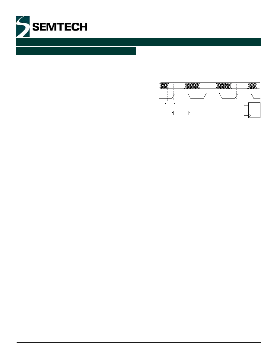
In this example, the ICs responsible for distributing the
clock and data signals may suffer several nanoseconds
of variation due to:
1)
DTpd: part to part
2)
DTpd: channel to channel (within a part)
3)
DTpd+/-: different propagation delays for a
positive vs. negative transition
4)
DTr/f: rise / fall time mismatches
5)
DTpd vs. frequency, duty cycle, and pattern
6)
DTpd vs. environmental changes, particularly
temperature and supply voltage
7)
Transmission line imperfections and mismatches.
Adding up all these error terms yields the total timing
uncertainty.
But as long as the relationship
(Total Error) + Ts + Thold
T
holds true, the system will still function properly.
A worst case system level error of several nanoseconds
(~3 ns) is quite reasonable using multiple instances of
most standard components. With a setup and hold time
of ~2 ns each, a 100 MHz system works with several
nanoseconds of margin.
Total Error + Ts + Thold = ~3 ns + ~2 ns + ~2 ns
@ 7 ns 10 ns
General Information
DATA
Example A:
CLK
D
CLK
tHOLD
ts
F = 100MHz
T = 10ns
相關(guān)PDF資料 |
PDF描述 |
|---|---|
| EPL10P8BD | UV-Erasable/OTP PLD |
| EPL10P8BP | UV-Erasable/OTP PLD |
| EPL12P6BD | UV-Erasable/OTP PLD |
| EPL241ED | UV-Erasable/OTP PLD |
| EPL241EJ | UV-Erasable/OTP PLD |
相關(guān)代理商/技術(shù)參數(shù) |
參數(shù)描述 |
|---|---|
| EPIC1741GW | 制造商:Vishay Semiconductors 功能描述: |
| EPIC3T144C8 | 制造商:未知廠家 制造商全稱:未知廠家 功能描述:技術(shù)資料 |
| EPIC-5536 | 制造商:AAEON 制造商全稱:AAEON 功能描述:EPIC Board with Onboard AMD Geode LX800 (500 MHz) Processor |
| EPIC-5537 | 制造商:AAEON 制造商全稱:AAEON 功能描述:Onboard AMD Geodea?¢ LX 800 Processor |
| EPIC-5537W1 | 制造商:AAEON 制造商全稱:AAEON 功能描述:Onboard AMD Geodea?¢ LX 800 Processor 500 MHz |
發(fā)布緊急采購,3分鐘左右您將得到回復(fù)。