- 您現(xiàn)在的位置:買賣IC網(wǎng) > PDF目錄97907 > ELH0101 Power Operational Amplifier PDF資料下載
參數(shù)資料
| 型號: | ELH0101 |
| 元件分類: | 運算放大器 |
| 英文描述: | Power Operational Amplifier |
| 中文描述: | 功率運算放大器 |
| 文件頁數(shù): | 2/16頁 |
| 文件大小: | 326K |
| 代理商: | ELH0101 |
ELH010188385089012YX
Power Operational Amplifier
Applications Information
Contd
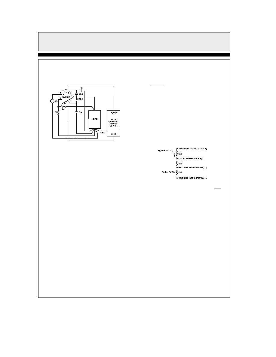
Every attempt should be made to achieve a sin-
gle point ground system as shown in the figure
below
0101 – 14
Bypass capacitor CBX should be used if the lead
lengths of bypass capacitors CB are long If a sin-
gle point ground system is not possible keep sig-
nal load and power supply from intermingling
as much as possible For further information on
proper grounding techniques refer to ‘‘Grounding
and Shielding Techniques in Instrumentation’’
by Morrison and ‘‘Noise Reduction Techniques
in Electronic Systems’’ by Ott (both published
by John Wiley and Sons)
Leads or PC board traces to the supply pins
short circuit current limit pins and the output
pin must be substantial enough to handle the
high currents that the ELH0101 is capable of
producing
Short Circuit Current Limiting
Should current limiting of the output not be nec-
essary SCa should be shorted to Va and SCb
should be shorted to Vb Remember that the
short circuit current limit is dependent upon the
total resistance seen between the supply and cur-
rent limit pins This total resistance includes the
desired resistor plus leads PC Board traces and
solder joints
Assuming a zero TCR current lim-
it resistor typical temperature coefficient of the
short circuit will be approximately 03%
Thermal Resistance
The thermal resistance between two points of a
conductive system is expressed as
i12 e
T1 b T2
PD
CW
(1)
where subscript order indicates the direction of
heat flow A simplified heat transfer circuit for a
cased semiconductor and heatsink system is
shown in the figure below
The circuit is valid only if the system is in ther-
mal equilibrium (constant heat flow) and there
are indeed single specific temperatures TJ TC
and TS (no temperature distribution in junction
case or heatsink) Nevertheless this is a reason-
able approximation of actual performance
0101 – 15
Short circuit current will be limited to approximately
06
RSC
The junction-to-case thermal resistance
iJC
specified in the data sheet depends upon the ma-
terial and size of the package die size and thick-
ness and quality of the die bond to the case or
lead frame The case-to-heatsink thermal resist-
ance
iCS depends on the mounting of the device
to the heatsink and upon the area and quality of
the contact surface Typical
iCS for a TO-3 pack-
age is 05 CW to 07 CW
and 03 CW to
05 CW using silicone grease
The heatsink to ambient thermal resistance
iSA
depends on the quality of the heatsink and the
ambient conditions
10
相關PDF資料 |
PDF描述 |
|---|---|
| ELH0101AK | Power Operational Amplifier |
| ELH0101K | Power Operational Amplifier |
| EM-SERIES | ASIC |
| EM08MR32UM | Dual Regulator-Synchronous Rectified Buck PWM and Linear Power Controller; Temperature Range: 0°C to 70°C; Package: 16-QFN |
| EM22003 | ACPI Regulator/Controller for Dual Channel DDR Memory Systems; Temperature Range: 0°C to 70°C; Package: 20-QFN |
相關代理商/技術參數(shù) |
參數(shù)描述 |
|---|---|
| ELH0101ACK | 制造商:未知廠家 制造商全稱:未知廠家 功能描述:Voltage-Feedback Operational Amplifier |
| ELH0101ACK/E+ | 制造商:未知廠家 制造商全稱:未知廠家 功能描述:Voltage-Feedback Operational Amplifier |
| ELH0101AK | 制造商:ELANTEC 制造商全稱:ELANTEC 功能描述:Power Operational Amplifier |
| ELH0101AK/883B | 制造商:E 功能描述: |
| ELH0101CK | 制造商:未知廠家 制造商全稱:未知廠家 功能描述:Voltage-Feedback Operational Amplifier |
發(fā)布緊急采購,3分鐘左右您將得到回復。