- 您現(xiàn)在的位置:買賣IC網(wǎng) > PDF目錄378593 > DSP202JP 16-bit fixed point DSP with Flash PDF資料下載
參數(shù)資料
| 型號(hào): | DSP202JP |
| 元件分類: | 數(shù)字信號(hào)處理 |
| 英文描述: | 16-bit fixed point DSP with Flash |
| 中文描述: | 具有閃存的 16 位定點(diǎn) DSP |
| 文件頁(yè)數(shù): | 18/19頁(yè) |
| 文件大小: | 106K |
| 代理商: | DSP202JP |
第1頁(yè)第2頁(yè)第3頁(yè)第4頁(yè)第5頁(yè)第6頁(yè)第7頁(yè)第8頁(yè)第9頁(yè)第10頁(yè)第11頁(yè)第12頁(yè)第13頁(yè)第14頁(yè)第15頁(yè)第16頁(yè)第17頁(yè)當(dāng)前第18頁(yè)第19頁(yè)
DSP201/202
18
USING DSP201 AND DSP202 WITH ADI DSP ICS
When using the DSP201 or DSP202 with the ADSP2101 or
ADSP2105, the processors need to be programmed to trans-
mit the data with the MSB first.
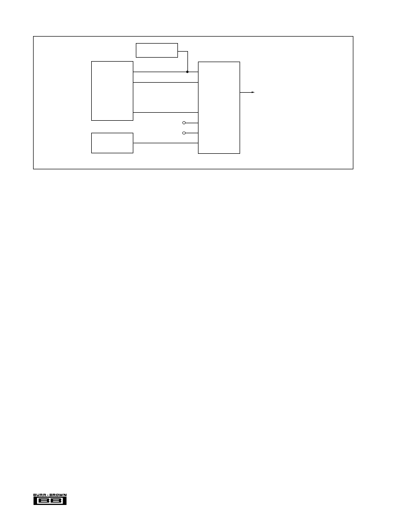
Figure 14 shows the connections required to generate an
analog output channel using an ADSP2105 with the DSP201.
The same basic circuit can also be used to connect a DSP201
to the ADSP2101.
Figure 6 indicates how to build a complete analog input and
analog output system using either the ADSP2101 or
ADSP2105 with a DSP201 and a Burr-Brown DSP101 A/D.
The two serial ports on the ADSP2101 can also be used with
the DSP202 to make two complete analog output channels
as noted in footnote 2 of Figure 10.
USING DSP201 AND
DSP202 WITH AT&T DSP ICS
Figures 15, 16 and 17 show how to use the DSP201 and
DSP202 with the DSP16 and DSP32C in different modes.
The DSP IC needs to be programmed to transmit data with
the MSB first, and the DSP201 or DSP202 needs to have
SSF (Select Sync Format on pin 9) tied LOW so that the
FIGURE 14. Using DSP201 with ADSP-2105.
D/As will output an appropriate active Low synchronization
pulse after a Convert Command is received.
Figures 15 and 17 show the DSP32C and DSP16 respec-
tively used with the DSP201 in the 16-bit Mode to generate
a single analog output channel. With a 12MHz Bit Clock and
the 24 Bit Clock cycles required by the DSP201 and DSP202
between Convert Commands, the output of Figure 15 can be
updated at a full 500kHz (12MHz/24 = 500kHz.)
Figure 16 shows how to drive two analog output channels
from a single 32-bit serial port on the DSP32C, using the
Cascade Mode on the DSP202. With a 12MHz Bit Clock
and the 40 Bit Clock cycles required between Convert
Commands by the DSP for internal logic overhead, this
circuit can update two separate analog outputs at 300kHz
each from a single serial port (12MHz/40 = 300kHz.)
Figure 6 indicates how to build a complete analog input and
analog output system using a DSP32C or DSP16 with a
DSP201 and a Burr-Brown DSP101 A/D.
Figure 7 shows a two channel analog output system using a
single DSP202 with two DSP32Cs or two DSP16s.
TTL Bit
Clock
12
13
11
9
10
15
XCLK
SIN
SYNC
SSF
SWL
CONV
±3V Analog Output
21
VOUT
DSP201
Conversion Rate
Generator
SCLK1
DT1
(1)
ADSP2105
NOTE: (1) 16-bit MSB first data.
+5V
+5V
TFS1
相關(guān)PDF資料 |
PDF描述 |
|---|---|
| DSP202KP | 16-bit fixed point DSP with Flash |
| DSP56004FJ81 | SYMPHONY AUDIO DSP FAMILY 24-BIT DIGITAL SIGNAL PROCESSORS |
| DSP56004ROM | SYMPHONY AUDIO DSP FAMILY 24-BIT DIGITAL SIGNAL PROCESSORS |
| DSP56721 | SymphonyTM DSP56720 / DSP56721 Multi-Core Audio Processors |
| DSPA56720AG | SymphonyTM DSP56720 / DSP56721 Multi-Core Audio Processors |
相關(guān)代理商/技術(shù)參數(shù) |
參數(shù)描述 |
|---|---|
| DSP202KP | 制造商:BB 制造商全稱:BB 功能描述:DSP-Compatible Single/Dual DIGITAL-TO-ANALOG CONVERTERS |
| DSP-204 | 制造商:SYNERGY 制造商全稱:SYNERGY MICROWAVE CORPORATION 功能描述:POWER DIVIDERS 0ì : 4-WAY |
| DSP-206 | 制造商:SYNERGY 制造商全稱:SYNERGY MICROWAVE CORPORATION 功能描述:POWER DIVIDERS 0ì : 4-WAY |
| DSP-207 | 制造商:SYNERGY 制造商全稱:SYNERGY MICROWAVE CORPORATION 功能描述:POWER DIVIDERS 0ì : 4-WAY |
| DSP-209 | 制造商:SYNERGY 制造商全稱:SYNERGY MICROWAVE CORPORATION 功能描述:POWER DIVIDERS 0ì : 2-WAY |
發(fā)布緊急采購(gòu),3分鐘左右您將得到回復(fù)。