- 您現(xiàn)在的位置:買賣IC網(wǎng) > PDF目錄11709 > DS1884AT+ (Maxim Integrated Products)IC SFP PON ONU CTRLR 24TQFN PDF資料下載
參數(shù)資料
| 型號: | DS1884AT+ |
| 廠商: | Maxim Integrated Products |
| 文件頁數(shù): | 28/92頁 |
| 文件大?。?/td> | 0K |
| 描述: | IC SFP PON ONU CTRLR 24TQFN |
| 標準包裝: | 500 |
| 系列: | * |
第1頁第2頁第3頁第4頁第5頁第6頁第7頁第8頁第9頁第10頁第11頁第12頁第13頁第14頁第15頁第16頁第17頁第18頁第19頁第20頁第21頁第22頁第23頁第24頁第25頁第26頁第27頁當(dāng)前第28頁第29頁第30頁第31頁第32頁第33頁第34頁第35頁第36頁第37頁第38頁第39頁第40頁第41頁第42頁第43頁第44頁第45頁第46頁第47頁第48頁第49頁第50頁第51頁第52頁第53頁第54頁第55頁第56頁第57頁第58頁第59頁第60頁第61頁第62頁第63頁第64頁第65頁第66頁第67頁第68頁第69頁第70頁第71頁第72頁第73頁第74頁第75頁第76頁第77頁第78頁第79頁第80頁第81頁第82頁第83頁第84頁第85頁第86頁第87頁第88頁第89頁第90頁第91頁第92頁
DS1884
SFP and PON ONU Controller
with Digital LDD Interface
34
Maxim Integrated
Power Leveling
The DS1884 supports power leveling as described in
G.984.2. The POW_LEV[1:0] bits in UPDATE A2h Lower
Memory, Register 6Fh allow for three power level set-
tings: 0dB, -3dB, and -6dB. Depending on the operation
mode, a combination of SET_IMOD and the KRMD bits
(MAX3710 TXCTRL3 register) are adjusted to meet these
power-level settings. The KRMD bits adjust the gain of
the APC loop and extinction ratio loop.
Manual MAX3710 Operations
The master interface is controllable using four registers
in the DS1884: 3WCTRL, ADDRESS, WRITE, READ.
Commands can be manually issued while the DS1884 is
in normal operation mode. It is also possible to suspend
normal 3-wire commands so that only manual operation
commands are sent (3WCTRL, A2h Table 04h, Register
I2C Communication
I2C Definition
The following terminology is commonly used to describe
I2C data transfers.
Master Device: The master device controls the slave
devices on the bus. The master device generates SCL
clock pulses and START and STOP conditions.
Slave Devices: Slave devices send and receive data
at the master’s request.
Bus Idle or Not Busy: Time between STOP and
START conditions when both SDA and SCL are inac-
tive and in their logic-high states.
START Condition: A START condition is generated by
the master to initiate a new data transfer with a slave.
Transitioning SDA from high to low while SCL remains
high generates a START condition. See Figure 18 for
applicable timing.
STOP Condition: A STOP condition is generated
by the master to end a data transfer with a slave.
Transitioning SDA from low to high while SCL remains
high generates a STOP condition. See Figure 18 for
applicable timing.
Repeated START Condition: The master can use a
repeated START condition at the end of one data transfer
to indicate that it will immediately initiate a new data trans-
fer following the current one. Repeated STARTs are com-
monly used during read operations to identify a specific
memory address to begin a data transfer. A repeated
START condition is issued identically to a normal START
condition. See Figure 18 for applicable timing.
Bit Write: Transitions of SDA must occur during the
low state of SCL. The data on SDA must remain valid
and unchanged during the entire high pulse of SCL
plus the setup and hold time requirements (Figure 18).
Data is shifted into the device during the rising edge
of the SCL.
Bit Read: At the end a write operation, the master
must release the SDA bus line for the proper amount
of setup time before the next rising edge of SCL during
a bit read (Figure 18). The device shifts out each bit of
data on SDA at the falling edge of the previous SCL
pulse and the data bit is valid at the rising edge of the
current SCL pulse. Remember that the master gener-
ates all SCL clock pulses, including when it is reading
bits from the slave.
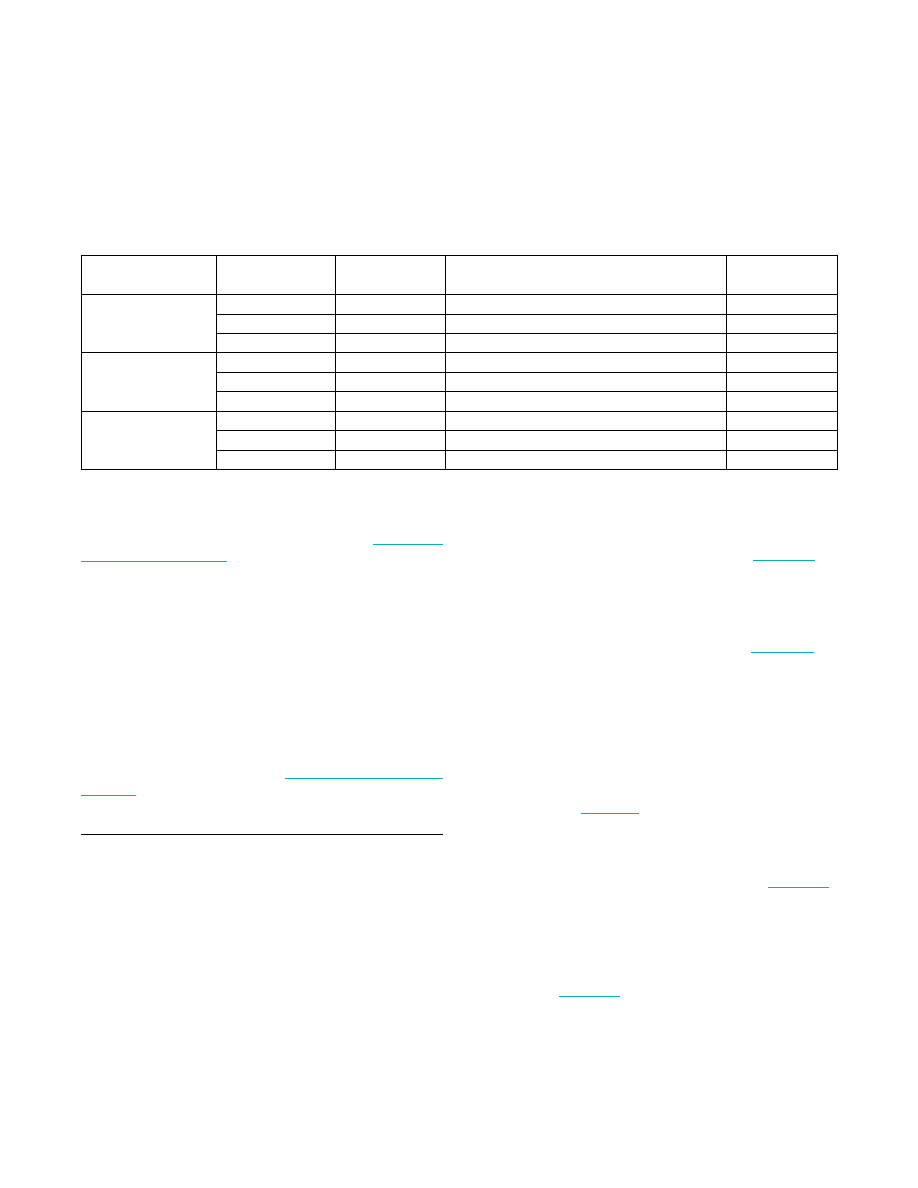
Table 13. Power Leveling Details
LOOP OPERATING
MODE
POWER LEVEL
(dB)
POW_LEV[1:0]
MODULATION CHANGE
KRMD[2:1]
(MAX3710)
Open Loop
0
00
None
1X
-3
01
Right-shift value written to SET_IMOD once
01
-6
11
Right-shift value written to SET_IMOD twice
00
APC Loop
0
00
None
1X
-3
01
Right-shift value written to SET_IMOD once
01
-6
11
Right-shift value written to SET_IMOD twice
00
Dual Closed Loop
0
00
None
1X
-3
01
None
01
-6
11
None
00
相關(guān)PDF資料 |
PDF描述 |
|---|---|
| GTC06AF-22-22P | CONN PLUG 4POS STRAIGHT W/PINS |
| V28C28H100BL2 | CONVERTER MOD DC/DC 28V 100W |
| V28C28H100BG | CONVERTER MOD DC/DC 28V 100W |
| D38999/20WE99SN | CONN RCPT 23POS WALL MNT W/SCKT |
| D38999/24JD18SN | CONN RCPT 18POS JAM NUT W/SCKT |
相關(guān)代理商/技術(shù)參數(shù) |
參數(shù)描述 |
|---|---|
| DS1884AT+ | 功能描述:ADC / DAC多通道 SFP and PON ONU Controller RoHS:否 制造商:Texas Instruments 轉(zhuǎn)換速率: 分辨率:8 bit 接口類型:SPI 電壓參考: 電源電壓-最大:3.6 V 電源電壓-最小:2 V 最大工作溫度:+ 85 C 安裝風(fēng)格:SMD/SMT 封裝 / 箱體:VQFN-40 |
| DS1884AT+T | 功能描述:ADC / DAC多通道 SFP and PON ONU Controller RoHS:否 制造商:Texas Instruments 轉(zhuǎn)換速率: 分辨率:8 bit 接口類型:SPI 電壓參考: 電源電壓-最大:3.6 V 電源電壓-最小:2 V 最大工作溫度:+ 85 C 安裝風(fēng)格:SMD/SMT 封裝 / 箱體:VQFN-40 |
| DS1884T+ | 功能描述:ADC / DAC多通道 SFP+ Controller w/ Digi LDD Interface RoHS:否 制造商:Texas Instruments 轉(zhuǎn)換速率: 分辨率:8 bit 接口類型:SPI 電壓參考: 電源電壓-最大:3.6 V 電源電壓-最小:2 V 最大工作溫度:+ 85 C 安裝風(fēng)格:SMD/SMT 封裝 / 箱體:VQFN-40 |
| DS1884T+T | 功能描述:ADC / DAC多通道 SFP+ Controller w/ Digi LDD Interface RoHS:否 制造商:Texas Instruments 轉(zhuǎn)換速率: 分辨率:8 bit 接口類型:SPI 電壓參考: 電源電壓-最大:3.6 V 電源電壓-最小:2 V 最大工作溫度:+ 85 C 安裝風(fēng)格:SMD/SMT 封裝 / 箱體:VQFN-40 |
| DS1886 | 制造商:未知廠家 制造商全稱:未知廠家 功能描述:帶有數(shù)字LDD接口的SFP和PON ONU控制器 |
發(fā)布緊急采購,3分鐘左右您將得到回復(fù)。