- 您現(xiàn)在的位置:買賣IC網(wǎng) > PDF目錄171225 > DS1862AB+ (MAXIM INTEGRATED PRODUCTS INC) SPECIALTY CONSUMER CIRCUIT, PBGA25 PDF資料下載
參數(shù)資料
| 型號: | DS1862AB+ |
| 廠商: | MAXIM INTEGRATED PRODUCTS INC |
| 元件分類: | 消費家電 |
| 英文描述: | SPECIALTY CONSUMER CIRCUIT, PBGA25 |
| 封裝: | 5 X 5 MM, ROHS COMPLIANT, CSBGA-25 |
| 文件頁數(shù): | 33/42頁 |
| 文件大?。?/td> | 586K |
| 代理商: | DS1862AB+ |
第1頁第2頁第3頁第4頁第5頁第6頁第7頁第8頁第9頁第10頁第11頁第12頁第13頁第14頁第15頁第16頁第17頁第18頁第19頁第20頁第21頁第22頁第23頁第24頁第25頁第26頁第27頁第28頁第29頁第30頁第31頁第32頁當(dāng)前第33頁第34頁第35頁第36頁第37頁第38頁第39頁第40頁第41頁第42頁
DS1862A
XFP Laser Control and Digital Diagnostic IC
______________________________________________________________________________________
39
I2C Operation Using
Packet Error Checking
Read Operation with
Packet Error Checking
Packet error checking during reads is supported by the
DS1862A. Information is transferred form the DS1862A
in much the same way as conventional I2C protocol,
however, an extra CRC field is added and checked.
The master still begins by sending the device address
(A0h for DS1862A), then the index pointer to the memo-
ry address of interest. The next byte transferred, how-
ever, is the value of the intended number of bytes to be
read. The calculation of the CRC-8 includes and
requires the explicit starting memory address to be
included as the second transferred byte (dummy write
byte). Next, the slave transfers the data back as the
master acknowledges. Only 1 to 128 bytes can be
sequentially read during one transmission while using
PEC. After the master reads the intended number of
bytes, the CRC-8 value is transmitted by the DS1862A.
The master ends the communication with a NACK and
a STOP. See Figure 16 for a graphical representation.
The CRC-8 is calculated starting with the MSB of the
memory address pointer, number of bytes to read, and
the read data. The master can then verify the CRC-8
value and reject the read data if the CRC-8 value does
not correspond to the received CRC value. The CRC-8
must be calculated by using the following polynomial
for both reads and writes:
C(x) = X8 +X2 + X + 1
Write Operation with
Packet Error Checking
Packet error checking during writes is also supported
by the DS1862A. Information is written to the DS1862A
in much the same way as conventional I2C protocol,
however, an extra CRC field is added and checked.
The master still begins by sending the device address,
then the index pointer to the memory address of inter-
est. The next byte, however, is the value of the intended
number of bytes to be written. The calculation of the
XXXXXXXX
10
1
0
10
1
0
10
1
0
10
1
0
10
1
0
10
1
0
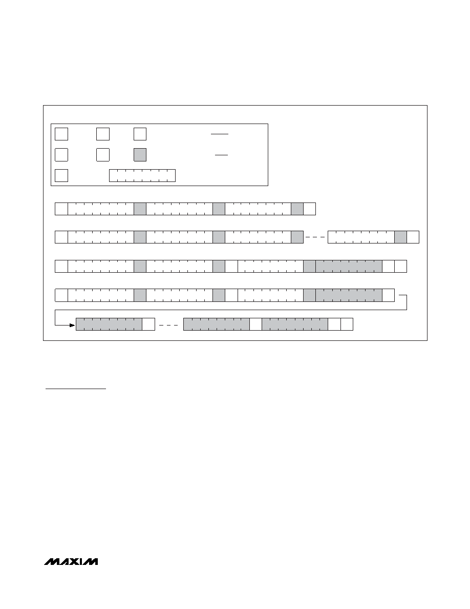
COMMUNICATIONS KEY
WRITE A SINGLE BYTE
WRITE UP TO A 4-BYTE PAGE WITH A SINGLE TRANSACTION
READ A SINGLE BYTE WITH A DUMMY WRITE CYCLE TO SET THE ADDRESS COUNTER
READ MULTIPLE BYTES WITH A DUMMY WRITE CYCLE TO SET THE ADDRESS COUNTER
8-BIT ADDRESS OR DATA
WHITE BOXES INDICATE THE MASTER IS
CONTROLLING SDA
THE FIRST BYTE SENT AFTER A START CONDITION IS
ALWAYS THE SLAVE ADDRESS FOLLOWED BY THE
READ/WRITE BIT.
SHADED BOXES INDICATE THE SLAVE IS
CONTROLLING SDA
START
ACK
NOT
ACK
S
A
P
A
ASR
SR
A
P
N
P
N
P
A
DATA
MEMORY ADDRESS
DATA
AA
A
PN
SR
STOP
REPEATED
START
NOTE:
ALL BYTES ARE SENT MOST SIGNIFICANT BIT FIRST.
Figure 15. I2C Communications Examples
相關(guān)PDF資料 |
PDF描述 |
|---|---|
| DS1862AB+T&R | SPECIALTY CONSUMER CIRCUIT, PBGA25 |
| DS1868-100-IND | 100K DIGITAL POTENTIOMETER, 2-WIRE SERIAL CONTROL INTERFACE, 256 POSITIONS, PDIP14 |
| DS2-320-2AR | DIP20, IC SOCKET |
| DS1-314-1AR | DIP14, IC SOCKET |
| DS3-328-1AR | DIP28, IC SOCKET |
相關(guān)代理商/技術(shù)參數(shù) |
參數(shù)描述 |
|---|---|
| DS1862AB+ | 功能描述:激光驅(qū)動器 XFP Laser Control & Digital Diagnostic RoHS:否 制造商:Micrel 數(shù)據(jù)速率:4.25 Gbps 工作電源電壓:3 V to 3.6 V 電源電流:80 mA 最大工作溫度:+ 85 C 封裝 / 箱體:QFN-16 封裝:Tube |
| DS1862AB+T&R | 制造商:Maxim Integrated Products 功能描述:XFP LASER CONTROL 25CSBGA - Tape and Reel 制造商:Maxim Integrated Products 功能描述:IC LASR CTRLR 7CHAN 5.5V 25CSBGA |
| DS1862AB+T&R | 功能描述:激光驅(qū)動器 XFP Laser Control & Digital Diagnostic RoHS:否 制造商:Micrel 數(shù)據(jù)速率:4.25 Gbps 工作電源電壓:3 V to 3.6 V 電源電流:80 mA 最大工作溫度:+ 85 C 封裝 / 箱體:QFN-16 封裝:Tube |
| DS1862AB+TR | 制造商:MAXIM 制造商全稱:Maxim Integrated Products 功能描述:XFP Laser Control and Digital Diagnostic IC |
| DS1862B | 功能描述:激光驅(qū)動器 RoHS:否 制造商:Micrel 數(shù)據(jù)速率:4.25 Gbps 工作電源電壓:3 V to 3.6 V 電源電流:80 mA 最大工作溫度:+ 85 C 封裝 / 箱體:QFN-16 封裝:Tube |
發(fā)布緊急采購,3分鐘左右您將得到回復(fù)。