- 您現(xiàn)在的位置:買賣IC網(wǎng) > PDF目錄376948 > DS1205S MultiKey Chip PDF資料下載
參數(shù)資料
| 型號: | DS1205S |
| 英文描述: | MultiKey Chip |
| 中文描述: | 多密鑰芯片 |
| 文件頁數(shù): | 3/17頁 |
| 文件大小: | 138K |
| 代理商: | DS1205S |
DS1205S
021798 3/17
COMMAND WORD STRUCTURE
Figure 2
(KK)
MSB
LSB
(AAAAAA)
FFFFFFFF
(KK)
C
(AAAAAA)
C
(KK) =
Two-bit number specifying which partition is to be accessed. 00 specifies subkey 0. 01 specifies
subkey 1. 10 specifies subkey 2. 11 specifies the scratchpad.
(KK)
C
=
Complement of (KK) on a bit-by-bit basis. If the numbers are not complements the command
word is invalid and no action will be taken.
(AAAAAA) =
Address field containing address bits that define the starting byte address of the partition to be
accessed.
(AAAAAA)
C
=
Complement of (AAAAAA) on a bit-by-bit basis. If the numbers are not complements the com-
mand word is invalid and no action will be taken.
FFFFFFFF =
Function code field. Specifies the action to be taken.
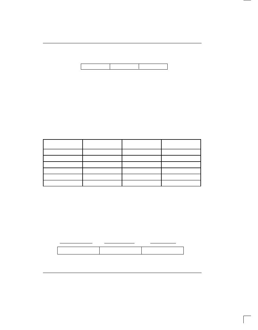
LOCATIONS, AND FUNCTION CODES FOR EACH COMMAND WORD
Figure 3
COMMAND
VALID PARTITION
CODE KK
VALID BYTE
ADDRESS AAAAAA
VALID FUNCTION
CODE FFFF FFFF
Set Scratchpad
11
0 - 63
1001 0110
Get Scratchpad
11
0 - 63
0110 1001
Set Secure Data
00, 01, 10
16 - 63
1001 1001
Get Secure Data
00, 01, 10
16 - 63
0110 0110
Set Security Match
00, 01, 10
000000
0101 1010
Move Block
00, 01, 10
000000
0011 1100
SECURE PARTITION COMMANDS
Each of the three secure partitions within the DS1205S
MultiKey is comprised of a 64-bit I.D. field, a 64-bit secu-
rity match code and a 384-bit secure data field (Figure
4). The three commands that operate on the secure
partitions are:
1) Set Security Match
2) Set Secure Data
3) Get Secure Data
As a guard against attackers, the security match code
can never be read. Similarly, tampering through repro-
gramming will immediately clear the entire secure parti-
tion.
SECURE PARTITION ORGANIZATION
Figure 4
ID FIELD
SECURITY MATCH FIELD
SECURE DATA FIELD
64 BITS
384 BITS
64 BITS
0
7
8
15
16
63
BYTES
相關(guān)PDF資料 |
PDF描述 |
|---|---|
| DS1205V | MultiKey |
| DS1208 | dallas semiconductor reliability report |
| DS1210 | Nonvolatile Controller Chip |
| DS1211 | Nonvolatile Controller x 8 Chip |
| DS1217M | Nonvolatile Read/Write Cartridge |
相關(guān)代理商/技術(shù)參數(shù) |
參數(shù)描述 |
|---|---|
| DS1205V | 制造商:DALLAS 制造商全稱:Dallas Semiconductor 功能描述:MultiKey |
| DS1206N | 制造商:未知廠家 制造商全稱:未知廠家 功能描述:Peripheral Interface |
| DS1206S | 制造商:Maxim Integrated Products 功能描述: |
| DS1206SN | 制造商:未知廠家 制造商全稱:未知廠家 功能描述:Peripheral Interface |
| DS1207 | 制造商:未知廠家 制造商全稱:未知廠家 功能描述:MISC MEMORY|MODULE|5PIN|PLASTIC |
發(fā)布緊急采購,3分鐘左右您將得到回復(fù)。