- 您現(xiàn)在的位置:買賣IC網(wǎng) > PDF目錄19022 > DC1369A-B (Linear Technology)BOARD DEMO 105MSPS LTC2260-14 PDF資料下載
參數(shù)資料
| 型號: | DC1369A-B |
| 廠商: | Linear Technology |
| 文件頁數(shù): | 31/34頁 |
| 文件大小: | 0K |
| 描述: | BOARD DEMO 105MSPS LTC2260-14 |
| 軟件下載: | QuikEval II System |
| 設計資源: | DC1369A Design Files |
| 標準包裝: | 1 |
| 系列: | * |
| 相關產(chǎn)品: | DC890B-ND - BOARD USB DATA COLLECTION |
第1頁第2頁第3頁第4頁第5頁第6頁第7頁第8頁第9頁第10頁第11頁第12頁第13頁第14頁第15頁第16頁第17頁第18頁第19頁第20頁第21頁第22頁第23頁第24頁第25頁第26頁第27頁第28頁第29頁第30頁當前第31頁第32頁第33頁第34頁

LTC2261-14
LTC2260-14/LTC2259-14
6
226114fc
For more information www.linear.com/LTC2261-14
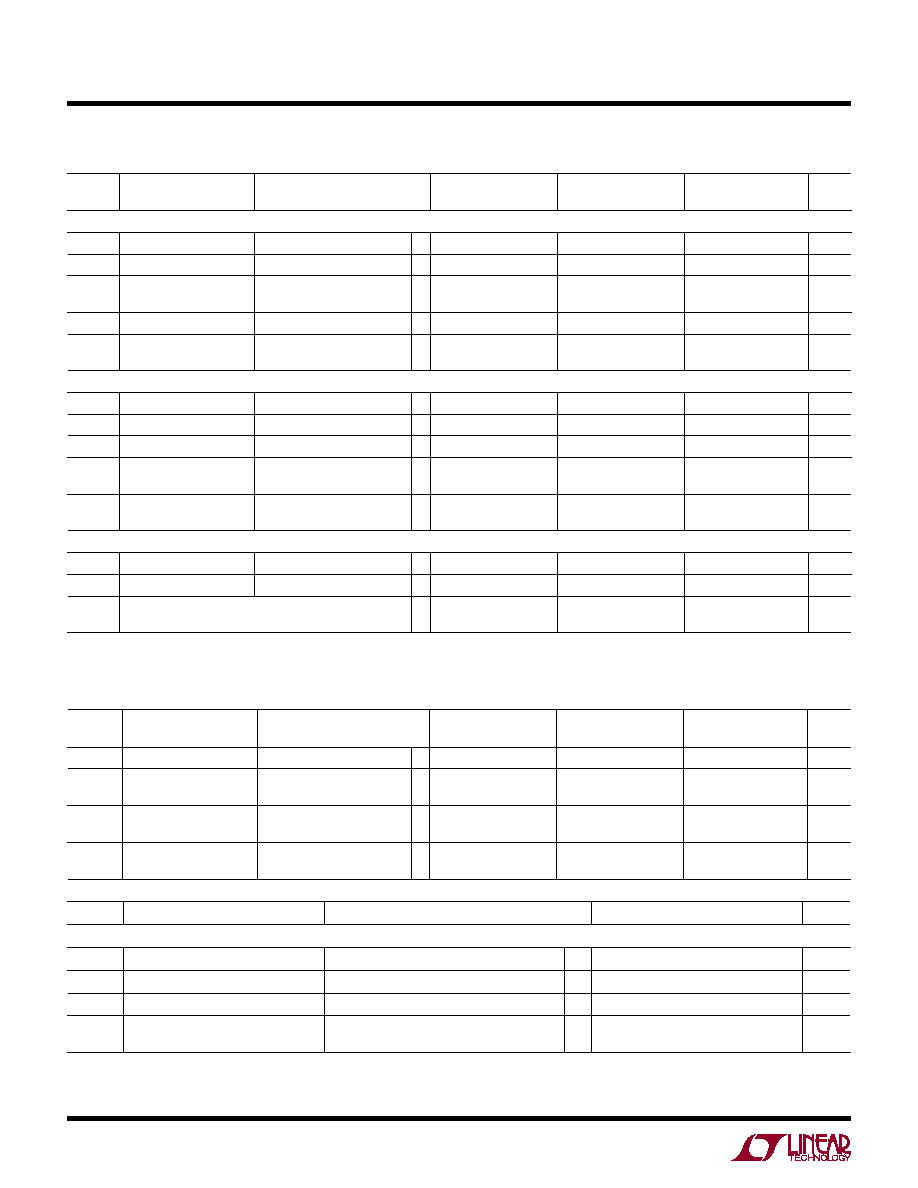
power requireMenTs The
l
denotes the specifications which apply over the full operating temperature
range, otherwise specifications are at TA = 25°C. (Note 9)
SYMBOL PARAMETER
CONDITIONS
LTC2261-14
LTC2260-14
LTC2259-14
UNITS
MIN
TYP
MAX
MIN
TYP
MAX
MIN
TYP
MAX
CMOS Output Modes: Full Data Rate and Double-Data Rate
VDD
Analog Supply Voltage
(Note 10)
l
1.7
1.8
1.9
1.7
1.8
1.9
1.7
1.8
1.9
V
OVDD
Output Supply Voltage
(Note 10)
l
1.1
1.9
1.1
1.9
1.1
1.9
V
IVDD
Analog Supply Current
DC Input
Sine Wave Input
l
70.5
71.8
83.2
58.6
59.8
69.1
49.2
50.2
58.1
mA
IOVDD
Digital Supply Current
Sine Wave Input, OVDD=1.2V
3.9
3.3
2.5
mA
PDISS
Power Dissipation
DC Input
Sine Wave Input, OVDD=1.2V
l
127
134
150
106
112
125
89
93
105
mW
LVDS Output Mode
VDD
Analog Supply Voltage
(Note 10)
l
1.7
1.8
1.9
1.7
1.8
1.9
1.7
1.8
1.9
V
OVDD
Output Supply Voltage
(Note 10)
l
1.7
1.9
1.7
1.9
1.7
1.9
V
IVDD
Analog Supply Current
Sine Wave Input
l
75.4
89
63.4
74.8
53.8
63.5
mA
IOVDD
Digital Supply Current
(0VDD = 1.8V)
Sine Input, 1.75mA Mode
Sine Input, 3.5mA Mode
l
20.7
40.5
26
47.8
20.7
40.5
26
47.8
20.7
40.5
26
47.8
mA
PDISS
Power Dissipation
Sine Input, 1.75mA Mode
Sine Input, 3.5mA Mode
l
173
209
207
246
151
187
182
221
134
170
161
201
mW
All Output Modes
PSLEEP
Sleep Mode Power
0.5
mW
PNAP
Nap Mode Power
9
mW
PDIFFCLK Power Increase with Differential Encode Mode Enabled
(No increase for Nap or Sleep Modes)
10
mW
TiMing characTerisTics The
l
denotes the specifications which apply over the full operating temperature
range, otherwise specifications are at TA = 25°C. (Note 5)
SYMBOL PARAMETER
CONDITIONS
LTC2261-14
LTC2260-14
LTC2259-14
UNITS
MIN
TYP
MAX
MIN
TYP
MAX
MIN
TYP
MAX
fS
Sampling Frequency
(Note 10)
l
1
125
1
105
1
80
MHz
tL
ENC Low Time (Note 8) Duty Cycle Stabilizer Off
Duty Cycle Stabilizer On
l
3.8
2.0
4
500
4.52
2.00
4.76
500
5.93
2.00
6.25
500
ns
tH
ENC High Time (Note 8) Duty Cycle Stabilizer Off
Duty Cycle Stabilizer On
l
3.8
2.0
4
500
4.52
2.00
4.76
500
5.93
2.00
6.25
500
ns
tAP
Sample-and-Hold
Acquisition Delay Time
0
ns
SYMBOL PARAMETER
CONDITIONS
MIN
TYP
MAX
UNITS
Digital Data Outputs (CMOS Modes: Full Data Rate and Double-Data Rate)
tD
ENC to Data Delay
CL = 5pF (Note 8)
l
1.1
1.7
3.1
ns
tC
ENC to CLKOUT Delay
CL = 5pF (Note 8)
l
1
1.4
2.6
ns
tSKEW
DATA to CLKOUT Skew
tD – tC (Note 8)
l
0
0.3
0.6
ns
Pipeline Latency
Full Data Rate Mode
Double-Data Rate Mode
5.0
5.5
Cycles
相關PDF資料 |
PDF描述 |
|---|---|
| 18 | LAMP T1-3/4 WEDGE BASE |
| 555 | LAMP INCAND T1-3/4 WEDGE BASE |
| 73 | LAMP T1-3/4 WEDGE BASE 14V |
| JX7011E0059.000000 | OSC 59MHZ 3.3V SMD |
| A0214X | 30MM IND CTRL PB OPERATOR |
相關代理商/技術參數(shù) |
參數(shù)描述 |
|---|---|
| DC1369A-C | 功能描述:BOARD DEMO 80MSPS LTC2259-14 RoHS:是 類別:未定義的類別 >> 其它 系列:* 標準包裝:1 系列:* 其它名稱:MS305720A |
| DC1369A-D | 制造商:Linear Technology 功能描述:14BIT ADC Eval Brd, Rq. DC1371 & DC1075 制造商:Linear Technology 功能描述:14BIT ADC Eval Brd, Rq. DC1371 & DC1075; Silicon Manufacturer:Linear Technology; Silicon Core Number:LTC2258-14; Kit Application Type:Data Converter; Application Sub Type:ADC; Kit Contents:Board, Guide |
| DC1369A-E | 制造商:Linear Technology 功能描述:14BIT ADC Eval Brd, Rq. DC1371 & DC1075 制造商:Linear Technology 功能描述:14BIT ADC Eval Brd, Rq. DC1371 & DC1075; Silicon Manufacturer:Linear Technology; Silicon Core Number:LTC2257-14; Kit Application Type:Data Converter; Application Sub Type:ADC; Kit Contents:Board, Guide |
| DC1369A-F | 制造商:Linear Technology 功能描述:14BIT ADC Eval Brd, Rq. DC1371 & DC1075 制造商:Linear Technology 功能描述:14BIT ADC Eval Brd, Rq. DC1371 & DC1075; Silicon Manufacturer:Linear Technology; Silicon Core Number:LTC2256-14; Kit Application Type:Data Converter; Application Sub Type:ADC; Kit Contents:Board, Guide |
| DC1369A-G | 功能描述:BOARD DEMO 125MSPS LTC2261-12 RoHS:是 類別:未定義的類別 >> 其它 系列:* 標準包裝:1 系列:* 其它名稱:MS305720A |
發(fā)布緊急采購,3分鐘左右您將得到回復。