- 您現(xiàn)在的位置:買賣IC網(wǎng) > PDF目錄362556 > AX1928EUB25 SMPS Controller PDF資料下載
參數(shù)資料
| 型號: | AX1928EUB25 |
| 英文描述: | SMPS Controller |
| 中文描述: | 開關(guān)電源控制器 |
| 文件頁數(shù): | 2/12頁 |
| 文件大小: | 303K |
| 代理商: | AX1928EUB25 |
M
Low-Output-Voltage, 800mA, PWM Step-Down
DC-DC Converters
2
_______________________________________________________________________________________
ABSOLUTE MAXIMUM RATINGS
BATT, PWM, POK, COMP,
SHDN
to GND ...............-0.3V to +6V
PGND to GND .......................................................-0.3V to +0.3V
LX, REF, FB to GND ................................-0.3V to (V
BATT
+ 0.3V)
Continuous Power Dissipation (T
A
= +70°C)
10-Pin μMAX (derate 5.6mW/°C above +70°C)...........444mW
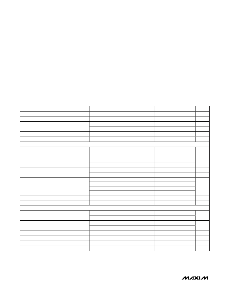
ELECTRICAL CHARACTERISTICS
(V
BATT
= 3.6V,
SHDN
= BATT, C
REF
= 0.1μF,
T
A
= 0°C to +85°C
, unless otherwise noted. Typical values are at T
A
= +25°C.)
Stresses beyond those listed under “Absolute Maximum Ratings” may cause permanent damage to the device. These are stress ratings only, and functional
operation of the device at these or any other conditions beyond those indicated in the operational sections of the specifications is not implied. Exposure to
absolute maximum rating conditions for extended periods may affect device reliability.
Operating Temperature Range ...........................-40°C to +85°C
Junction Temperature......................................................+150°C
Storage Temperature Range.............................-65°C to +150°C
Lead Temperature (soldering, 10s).................................+300°C
PARAMETER
CONDITIONS
MIN
2.6
2.15
TYP
MAX
5.5
2.55
240
UNITS
V
V
μA
mA
μA
μA
BATT Input Voltage
Undervoltage Lockout Threshold
V
BATT
rising or falling (35mV hysteresis)
No load, pulse skipping, PWM = GND
1MHz switching
2.35
140
2
190
0.1
Quiescent Current
Quiescent Current in Dropout
Shutdown Supply Current
REFERENCE AND ERROR AMP
340
10
SHDN
= GND
MAX1927R
MAX1928-15
MAX1928-18
MAX1928-25
MAX1928
MAX1927R
MAX1927R
MAX1928-15
MAX1928-18
MAX1928-25
0.738
1.477
1.773
2.462
5
0.75
1.5
1.8
2.5
10
10
250
210
175
125
1.25
0.5
0.762
1.523
1.827
2.538
15
150
FB Voltage Accuracy
V
μA
nA
FB Input Current
Transconductance (g
m
)
μS
Reference Voltage Accuracy
Reference Supply Rejection
PWM CONTROLLER
1.231
1.269
2
V
2.6V < V
BATT
< 5.5V
mV
V
BATT
= 3.6V
V
BATT
= 2.6V
V
BATT
= 3.6V
V
BATT
= 2.6V
0.25
0.3
0.17
0.2
0.48
1.3
0.13
-0.55
0.4
0.5
0.3
0.35
P-Channel On-Resistance
N-Channel
On-Resistance
Current-Sense Transresistance (R
CS
)
P-Channel Current-Limit Threshold
P-Channel Pulse-Skipping Current Threshold
N-Channel Negative Current-Limit Threshold
V/A
A
A
A
1.1
0.11
1.6
0.15
相關(guān)PDF資料 |
PDF描述 |
|---|---|
| AXDA1700DKT3C | Microprocessor |
| AXDA1700DKV3C | Microprocessor |
| AXDA1700DLT3C | Microprocessor |
| AXDA1700DLT3D | Microprocessor |
| AXDA1700DLV3C | Microprocessor |
相關(guān)代理商/技術(shù)參數(shù) |
參數(shù)描述 |
|---|---|
| ax1b-10a | 制造商:SAN-O 功能描述: |
| AX1B-2AMP | 制造商:MISCELLANEOUS 功能描述: |
| AX-1MC-01 | 制造商:Carlo Gavazzi 功能描述:SIDE AUX 1NC MINI CC |
| AX-1MF-10 | 制造商:Carlo Gavazzi 功能描述:SIDE AUX 1NO MINI FAST-ON |
| AX-1MS-10 | 制造商:Carlo Gavazzi 功能描述:SIDE AUX 1NO MINI SC |
發(fā)布緊急采購,3分鐘左右您將得到回復(fù)。