- 您現(xiàn)在的位置:買賣IC網(wǎng) > PDF目錄362556 > AX1928EUB25 SMPS Controller PDF資料下載
參數(shù)資料
| 型號: | AX1928EUB25 |
| 英文描述: | SMPS Controller |
| 中文描述: | 開關(guān)電源控制器 |
| 文件頁數(shù): | 10/12頁 |
| 文件大小: | 303K |
| 代理商: | AX1928EUB25 |
M
For the MAX1928:
Resistors R1 and R2 are external to the MAX1927 (see
the
Setting the Output Voltage
section). I
OUT(MAX)
is the
maximum output current, R
CS
= 0.48V/A, and g
m
=
250μS for the MAX1927. See the
Electrical Characteristics
table for MAX1928 g
m
values. Select the closest standard
C
C
value that gives an acceptable bandwidth.
3) Calculate the equivalent load impedance, R
L
, by:
4) Calculate the compensation resistance (R
C
) to can-
cel out the dominant pole created by the output
load and the output capacitance:
Solving for R
C
gives:
5) Calculate the high-frequency compensation pole to
cancel the zero created by the output capacitor
’
s ESR:
1
2
1
2
π
π
×
×
=
×
×
R
C
R
C
ESR
OUT
C
f
R
R
C
C
C
L
OUT
C
=
×
1
2
1
2
π
π
×
×
=
×
×
R
C
R
C
L
OUT
C
C
R
V
I
L
OUT
(
OUT MAX
=
)
C
V
I
R
g
f
C
OUT
(
OUT MAX
CS
m
C
=
×
(
)
×
)
1
1
2
π
Low-Output-Voltage, 800mA, PWM Step-Down
DC-DC Converters
10
______________________________________________________________________________________
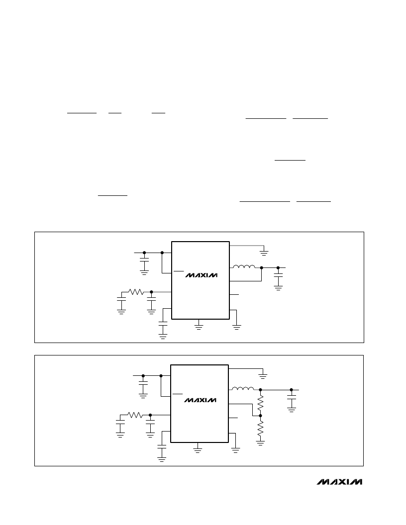
BATT
COMP
GND
REF
PGND
LX
POK
FB
V
IN
2.6V TO 5.5V
C1
10
μ
F
C2
10
μ
F
C
C
1200pF
R
C
18k
L1
CDRH4D18
4.7
μ
H
V
OUT
1.8V AT 800mA
SHDN
PWM
MAX1928-18
C
f
22pF
C3
0.1
μ
F
Figure 3. Applications Circuit for the MAX1928
BATT
COMP
REF
PGND
LX
POK
FB
V
IN
2.6V TO 5.5V
C1
10
μ
F
C2
10
μ
F
C
C
680pF
R
C
15k
L1
CDRH4D18
4.7
μ
H
V
OUT
1V AT 800mA
SHDN
MAX1927R
C
f
22pF
C3
0.1
μ
F
R1
16.5k
1%
R2
49.9k
1%
GND
PWM
Figure 4. Applications Circuit for the MAX1927
相關(guān)PDF資料 |
PDF描述 |
|---|---|
| AXDA1700DKT3C | Microprocessor |
| AXDA1700DKV3C | Microprocessor |
| AXDA1700DLT3C | Microprocessor |
| AXDA1700DLT3D | Microprocessor |
| AXDA1700DLV3C | Microprocessor |
相關(guān)代理商/技術(shù)參數(shù) |
參數(shù)描述 |
|---|---|
| ax1b-10a | 制造商:SAN-O 功能描述: |
| AX1B-2AMP | 制造商:MISCELLANEOUS 功能描述: |
| AX-1MC-01 | 制造商:Carlo Gavazzi 功能描述:SIDE AUX 1NC MINI CC |
| AX-1MF-10 | 制造商:Carlo Gavazzi 功能描述:SIDE AUX 1NO MINI FAST-ON |
| AX-1MS-10 | 制造商:Carlo Gavazzi 功能描述:SIDE AUX 1NO MINI SC |
發(fā)布緊急采購,3分鐘左右您將得到回復(fù)。