- 您現(xiàn)在的位置:買賣IC網(wǎng) > PDF目錄51299 > AT-31011-TR2G UHF BAND, Si, NPN, RF SMALL SIGNAL TRANSISTOR PDF資料下載
參數(shù)資料
| 型號: | AT-31011-TR2G |
| 元件分類: | 小信號晶體管 |
| 英文描述: | UHF BAND, Si, NPN, RF SMALL SIGNAL TRANSISTOR |
| 封裝: | ROHS COMPLIANT, PLASTIC PACKAGE-4 |
| 文件頁數(shù): | 9/10頁 |
| 文件大小: | 257K |
| 代理商: | AT-31011-TR2G |
8
AT-31011 Typical Scattering Parameters, VCE = 5 V, IC = 1 mA, Common Emitter, ZO = 50
Freq.
S11
S21
S12
S22
GHz
Mag
Ang
dB
Mag
Ang
dB
Mag
Ang
Mag
Ang
0.1
0.96
-7
11.10
3.59
174
-40.35
0.01
84
0.999
-2
0.5
0.94
-31
10.67
3.41
153
-26.95
0.04
69
0.96
-13
0.9
0.83
-54
9.93
3.14
133
-22.80
0.07
56
0.92
-22
1.0
0.81
-60
9.57
3.01
129
-22.18
0.08
53
0.91
-23
1.5
0.68
-86
8.41
2.63
108
-20.33
0.10
41
0.85
-31
1.8
0.62
-101
7.62
2.40
97
-19.85
0.10
35
0.81
-35
2.0
0.58
-110
7.27
2.31
91
-19.64
0.10
32
0.79
-37
2.4
0.52
-129
6.10
2.02
78
-19.50
0.11
28
0.76
-41
3.0
0.44
-157
4.78
1.73
62
-19.68
0.10
26
0.73
-45
4.0
0.42
161
2.90
1.40
40
-19.86
0.10
31
0.70
-55
5.0
0.45
125
1.33
1.17
21
-18.35
0.12
43
0.70
-65
AT-31011 Typical Noise Parameters,
Common Emitter, ZO = 50 , 5 V, IC = 1 mA
ΓOPT
Freq
Fmin[1]
Rn
GHz
dB
Mag
Ang
0.5[2]
0.5
0.92
13
0.85
0.9
0.6
0.85
29
0.73
1.8
1.1
0.68
67
0.46
2.4
1.6
0.55
98
0.28
Notes:
1. Matching constraints may make Fmin values associated with high |ΓOPT| values unachievable
in physical circuits. See Figure 2 for expected performance.
2. 0.5 GHz noise parameter values are extrapolated, not measured.
AT-31033 Typical Scattering Parameters, VCE = 5 V, IC = 1 mA, Common Emitter, ZO = 50
Freq.
S11
S21
S12
S22
GHz
Mag
Ang
dB
Mag
Ang
dB
Mag
Ang
Mag
Ang
0.1
0.95
-7
10.93
3.52
173
-37.78
0.01
85
0.999
-3
0.5
0.89
-31
10.24
3.25
147
-24.43
0.06
70
0.94
-15
0.9
0.73
-52
9.20
2.88
124
-20.49
0.09
59
0.88
-24
1.0
0.70
-57
8.75
2.74
119
-19.91
0.10
57
0.87
-26
1.5
0.49
-80
7.30
2.32
96
-18.15
0.12
49
0.79
-32
1.8
0.39
-93
6.41
2.09
85
-17.54
0.13
47
0.75
-36
2.0
0.34
-102
5.93
1.98
78
-17.19
0.14
46
0.73
-37
2.4
0.23
-122
4.77
1.73
66
-16.55
0.15
46
0.71
-40
3.0
0.13
-166
3.49
1.49
50
-15.35
0.17
49
0.68
-45
4.0
0.17
107
1.71
1.22
29
-12.83
0.23
51
0.66
-56
5.0
0.28
68
0.32
1.04
12
-9.96
0.32
48
0.64
-69
AT-31033 Typical Noise Parameters,
Common Emitter, ZO = 50 , 5 V, IC = 1 mA
ΓOPT
Freq
Fmin[1]
Rn
GHz
dB
Mag
Ang
0.5[2]
0.5
0.90
12
0.70
0.9
0.6
0.82
28
0.60
1.8
1.1
0.57
68
0.38
2.4
1.6
0.41
100
0.22
Notes:
1. Matching constraints may make Fmin values associated with high |ΓOPT| values unachievable
in physical circuits. See Figure 2 for expected performance.
2. 0.5 GHz noise parameter values are extrapolated, not measured.
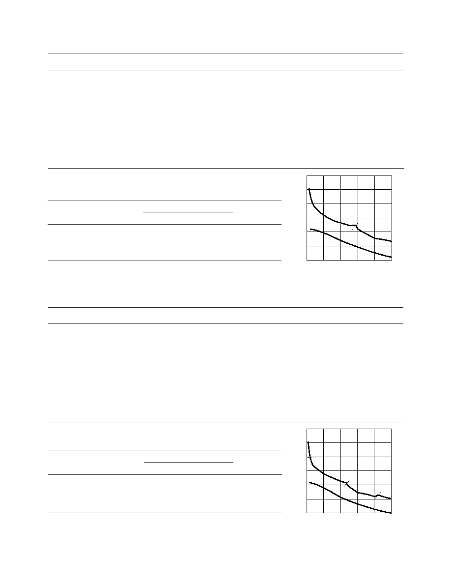
AT-31011 fig 23
GAIN
(dB)
0
FREQUENCY (GHz)
2
3
30
1
5
10
4
20
MSG
MAG
S21
Figure 23. AT-31011 Gains vs. Frequency at VCE = 5 V,
IC = 1 mA.
AT-31011 fig 24
GAIN
(dB)
0
FREQUENCY (GHz)
2
3
30
1
5
10
4
20
MSG
MAG
S21
MSG
Figure 24. AT-31033 Gains vs. Frequency at VCE = 5 V,
IC = 1 mA.
相關(guān)PDF資料 |
PDF描述 |
|---|---|
| AT-31033-BLKG | UHF BAND, Si, NPN, RF SMALL SIGNAL TRANSISTOR |
| AT-31011-BLKG | UHF BAND, Si, NPN, RF SMALL SIGNAL TRANSISTOR |
| AT-31033-TR1G | UHF BAND, Si, NPN, RF SMALL SIGNAL TRANSISTOR |
| AT-31011-TR1G | UHF BAND, Si, NPN, RF SMALL SIGNAL TRANSISTOR |
| AT-31033-TR2G | UHF BAND, Si, NPN, RF SMALL SIGNAL TRANSISTOR |
相關(guān)代理商/技術(shù)參數(shù) |
參數(shù)描述 |
|---|---|
| AT310-22/23-4 | 制造商:Block USA Inc. 功能描述:3 phase autotransformer,220-400V 10kVA |
| AT31033 | 制造商:未知廠家 制造商全稱:未知廠家 功能描述:TRANSISTOR | BJT | NPN | 5.5V V(BR)CEO | 20MA I(C) | SOT-23 |
| AT-31033 | 制造商:AGILENT 制造商全稱:AGILENT 功能描述:Low Current, High Performance NPN Silicon Bipolar Transistor |
| AT31033BLK | 制造商:未知廠家 制造商全稱:未知廠家 功能描述:TRANSISTOR | BJT | NPN | 5.5V V(BR)CEO | 20MA I(C) | SOT-143 |
| AT-31033-BLK | 制造商:AGILENT 制造商全稱:AGILENT 功能描述:Low Current, High Performance NPN Silicon Bipolar Transistor |
發(fā)布緊急采購,3分鐘左右您將得到回復(fù)。