- 您現(xiàn)在的位置:買賣IC網(wǎng) > PDF目錄375316 > AN207 (Vishay Intertechnology,Inc.) 12-ns DG611 Switch Family Combines Benefits of CMOS and DMOS Technologies PDF資料下載
參數(shù)資料
| 型號: | AN207 |
| 廠商: | Vishay Intertechnology,Inc. |
| 英文描述: | 12-ns DG611 Switch Family Combines Benefits of CMOS and DMOS Technologies |
| 中文描述: | 12納秒DG611開關系列組合的優(yōu)點CMOS和DMOS技術 |
| 文件頁數(shù): | 7/12頁 |
| 文件大小: | 149K |
| 代理商: | AN207 |
AN207
Vishay Siliconix
Document Number: 70605
03-Aug-99
www.vishay.com FaxBack 408-970-5600
6-7
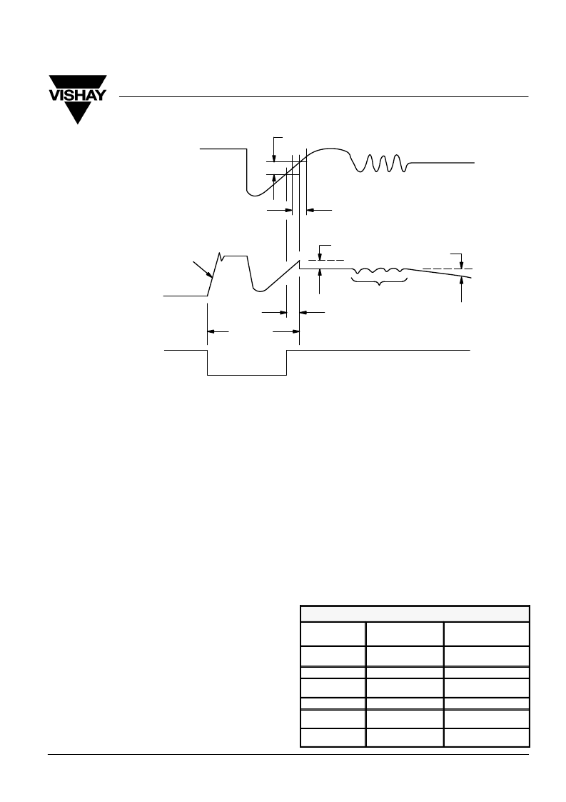
FIGURE 11.
Error Sources in Sample-and-Hold Circuits
Aperature Uncertainty (Jitter)
Aperature Error
Analog Input
Slew Rate
Hold Step
Droop Rate = dV/dt
Feedthrough
Aperature Delay
Aquisition
Time
Sample
Hold
Analog Output
Control
Because of non-ideal component characteristics, there are many
sources of error in a sample-and-hold circuit. Figure 11 illustrates
the most important ones. Table 1 lists these error sources and
shows how the DG611 characteristics reduce those errors and
improve overall circuit performance.
Figure 12 shows a closed loop sample-and-hold circuit. When
SW1 and SW2 are closed, the output buffer is forced to track
the analog input with a high degree of accuracy. SW3 improves
acquisition time by letting the input buffer follow the input signal
even during the hold periods. This circuit achieves high speed
and high accuracy.
Programmable Low-Pass Filter
Many
programmable by using analog switches to select different
component values into the circuit. Figure 13 illustrates a
low-pass filter where a single DG613 is used to change the
corner frequencies from 300 kHz to 400 kHz by selecting one
of two resistor pairs. Keeping the input and feedback resistor
values equal maintains unity gain. The DG613s low parasitic
capacitances improve frequency response and permit
operation at higher frequencies.
active
filter
implementations
can
be
made
Switched-Capacitor Filters
Switched-capacitor filters (SCFs) offer high accuracy and
excellent temperature stability. In addition, their cutoff
frequencies are programmable over a wide range by simply
changing the clock frequency.
Highly efficient audio frequency SCFs have been
commercially available for several years, but since their
sampling clocks need to be 25 to 100 times the signal
frequency, they have been limited to applications in the 30- to
50-kHz range.
Error Source
DG611
Parameter
Benefit
Acquisition Time
r
DS(on)
= 18
t
(on)
t
(off)
= 8 ns
t
(off)
= 8 ns
Faster sampling,settling
times
Aperature Delay
Minimal turn-off delay
Aperature
Uncertainty
Consistent propagation
delay
Hold Step
Q = 3 pC
Minimal switching glitches
Feed Through
Off Isolation = 74 dB @
5 MHz
Low capacitive coupling
Droop Rate
I
D(off)
= 0.25 nA
Guaranteed low
leakages
相關PDF資料 |
PDF描述 |
|---|---|
| AN2101 | NTSC/PAL signal processor IC for 510H color CCD cameras |
| AN2101FH | NTSC/PAL signal processor IC for 510H color CCD cameras |
| AN2108NFHQ | Camera Signal ProcessingCDS+ AGC+ Gamma |
| AN2141 | Video Camera Luminance Signal Processing Circuit |
| AN2493FH | Luminance and chrominance signal processing (PAL) IC for 8 mm VCR |
相關代理商/技術參數(shù) |
參數(shù)描述 |
|---|---|
| AN-2070 | 制造商:NSC 制造商全稱:National Semiconductor 功能描述:AVS Adaptor Board for USB AVS System Mainboards |
| AN-2074 | 制造商:NSC 制造商全稱:National Semiconductor 功能描述:LMZ1050xEXT Evaluation Board |
| AN-2084 | 制造商:NSC 制造商全稱:National Semiconductor 功能描述:LMZ1420xEXT/ LMZ1200xEXT Evaluation Board |
| AN209 | 制造商:未知廠家 制造商全稱:未知廠家 功能描述:Using Terminator Technology in Stratix & Stratix GX Devices |
| AN20-C10 | 制造商:SMC Corporation of America 功能描述:Silencer, Compact Resin, One-Touch, 10mm Port, 30 dB(A), 57.5mm, Model AN20-C10 制造商:SMC 功能描述:SY5000 silencer, compact resin type(0) |
發(fā)布緊急采購,3分鐘左右您將得到回復。