- 您現(xiàn)在的位置:買賣IC網(wǎng) > PDF目錄378403 > AN013 (Intersil Corporation) JT 128C 128#22D SKT RECP PDF資料下載
參數(shù)資料
| 型號: | AN013 |
| 廠商: | Intersil Corporation |
| 英文描述: | JT 128C 128#22D SKT RECP |
| 中文描述: | 人們始終想關(guān)于ICL8038知情權(quán) |
| 文件頁數(shù): | 1/4頁 |
| 文件大小: | 87K |
| 代理商: | AN013 |
1
1-888-INTERSIL or 321-724-7143
|
Copyright
Intersil Corporation 1999
Everything You Always Wanted to Know
About the ICL8038
Introduction
The 8038 is a function generator capable of producing sine,
square, triangular, sawtooth and pulse waveforms (some at
the same time). Since its introduction, marketing and appli-
cation engineers have been manning the phones explaining
the care and feeding of the 8038 to customers worldwide.
This experience has enabled us to form articulate responses
to the most frequently asked questions. So, with data sheet
and breadboard in hand, read on and be enlightened.
Question 1
I want to sweep the frequency externally but can only get a
range of 100:1 (or 50:1, or 10:1). Your data sheet says
1000:1. How much sweep range can I expect
Answer
Let’s look at what determines the output frequency. Start by
examining the circuit schematic at pin 8 in the upper left hand
corner. From pin 8 to pin 5 we have the emitter-base of NPN
Q
1
and the emitter-base of PNP Q
2
. Since these two diode
drops cancel each other (approximately), the potential at pins
8, 5, and 4 are the same. This means that the voltage from V+
to pin 8 is the same as the voltage across external resistors
R
A
and R
B
. This is a textbook example of a voltage across
two resistors which produce two currents to charge and dis-
charge a capacitor between two fixed voltages. This is also a
linear system. If the voltage across the resistors is dropped
from 10V to 1V, the frequency will drop by 10:1. Changing
from 1V to 0.1V will also change the frequency by 10:1.
Therefore, by causing the voltage across the external resis-
tors to change from say 10V to 10mV, the frequency can be
made to vary at least 1000:1. There are, however, several fac-
tors which make this large sweep range less than ideal.
Question 2
You say I can vary the voltage on pin 8 (FM sweep input) to
get this large range, yet when I short pin 8 to V+ (pin 6), the
ratio is only around 100:1.
Answer
This is often true. With pin 8 shorted to V+, a check on the
potentials across the external R
A
and R
B
will show 100mV
or more. This is due to the V
BE
mismatch between Q
1
and
Q
2
(also Q
1
and Q
3
) because of the geometries and current
levels involved. Therefore, to get smaller voltages across
these resistors, pin 8 must be raised above V+.
Question 3
How can I raise pin 8 above V+ without a separate power
supply
Answer
First of all, the voltage difference need only be a few hundred
millivolts so there is no danger of damaging the 8038. One
way to get this higher potential is to lower the supply voltage
on the 8038 and external resistors. The simplest way to do
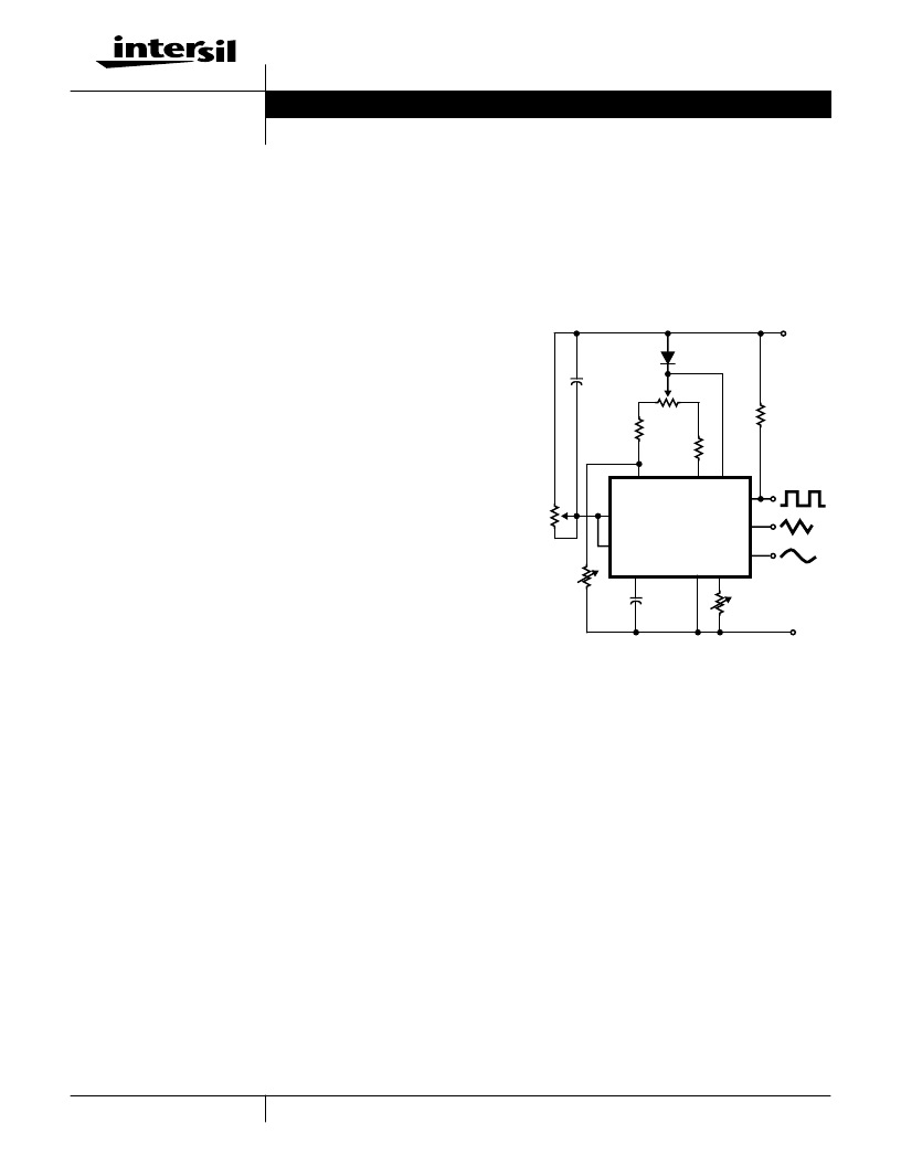
this is to include a diode in series with pin 6 and resistors R
A
and R
B
. See Figure 1. This technique should increase the
sweep range to 1000:1.
Question 4
O.K., now I can get a large frequency range, but I notice that
the duty cycle and hence my distortion changes at the low-
est frequencies.
Answer
This is caused partly by a slight difference in the V
BE
s of Q
2
and Q
3
. In trying to manufacture two identical transistors, it is
not uncommon to get V
BE
differences of several millivolts or
more. In the standard 8038 connection with pins 7 and 8 con-
nected together, there are several volts across R
A
and R
B
and
this small mismatch is negligible. However, in a swept mode
with the voltage at pin 8 near V+ and only tens of millivolts
across R
A
and R
B
, the V
BE
mismatch causes a larger mis-
match in charging currents, hence the duty cycle changes. For
lowest distortion then, it is advisable to keep the minimum
voltage across R
A
and R
B
around 100mV. This would of
course, limit the frequency sweep range to around 100:1.
FIGURE 1. VARIABLE AUDIO OSCILLATOR, 20Hz TO 20kHz
1N457
DUTY
CYCLE
1K
4.7K
R
A
4.7K
R
B
0.1
μ
F
+15V
15K
-15V
DISTORTION
100K
0.0047
μ
F
10M
100K
FREQUENCY
LOG POT
2
3
4
5
6
7
8
9
10
11
12
Application Note
November 1996
AN013.1
Author: Bill O’Neil
相關(guān)PDF資料 |
PDF描述 |
|---|---|
| AN1025 | Converting A 5.0V Supply Rail To A Regulated 3.0V |
| AN1034 | Analog Switch and Multiplexer Applications |
| AN1042 | High Fidelity Switching Audio Amplifiers Using TMOS Power MOSFETs |
| AN1042D | High Fidelity Switching Audio Amplifiers Using TMOS Power MOSFETs |
| AN1062 | Circular Connector; No. of Contacts:6; Series:MS27508; Body Material:Aluminum; Connecting Termination:Crimp; Connector Shell Size:8; Circular Contact Gender:Socket; Circular Shell Style:Box Mount Receptacle; Insert Arrangement:8-35 RoHS Compliant: No |
相關(guān)代理商/技術(shù)參數(shù) |
參數(shù)描述 |
|---|---|
| AN0130 | 制造商:SUPERTEX 制造商全稱:SUPERTEX 功能描述:8 Channel Power MOSFET Array Monolithic N-channel Enchancement Mode |
| AN0130NA | 制造商:SUPERTEX 制造商全稱:SUPERTEX 功能描述:8 Channel Power MOSFET Array Monolithic N-channel Enchancement Mode |
| AN0130NB | 制造商:SUPERTEX 制造商全稱:SUPERTEX 功能描述:8 Channel Power MOSFET Array Monolithic N-channel Enchancement Mode |
| AN0130ND | 制造商:SUPERTEX 制造商全稱:SUPERTEX 功能描述:8 Channel Power MOSFET Array Monolithic N-channel Enchancement Mode |
| AN0132 | 制造商:SUPERTEX 制造商全稱:SUPERTEX 功能描述:8 Channel Power MOSFET Array Monolithic N-channel Enchancement Mode |
發(fā)布緊急采購,3分鐘左右您將得到回復(fù)。