- 您現(xiàn)在的位置:買賣IC網(wǎng) > PDF目錄378403 > AN-994-1 (International Rectifier) MAXIMIZING THE EFFECTIVENESS OF YOUR SMD ASSEMBLIES PDF資料下載
參數(shù)資料
| 型號: | AN-994-1 |
| 廠商: | International Rectifier |
| 英文描述: | MAXIMIZING THE EFFECTIVENESS OF YOUR SMD ASSEMBLIES |
| 中文描述: | 最大限度地發(fā)揮你的貼片組件效果 |
| 文件頁數(shù): | 5/7頁 |
| 文件大?。?/td> | 120K |
| 代理商: | AN-994-1 |
5 of 7
150
Section IV: Solder Pastes:
There are a wide variety of solder pastes available for
surface mounting applications. Typical solder pastes
are composed of a homogeneous mixture of pre
alloyed solder powder with a specific grain size.
Fluxes are also provided in the solder paste mixture as
a necessary component of the surface mounting
process.
In today’s densely populated assemblies, pin spacing
of SMD components has significantly been reduced.
Pin spacing of less than 0.4mm is common which
poses problem such as solder bridging, insufficient
solder on the lead and device placement accuracy.
Solder stencil thickness, dimension and registration
accuracy, solder paste composition and particle size
are all critical to successful soldering of these
assemblies.
With the advanced state of the art of fine pitch device
technology, a simple guideline for the choice of solder
paste is outside the scope of this document. The
customer should seek expert guidance from the solder
paste vendor and PCB board fabricator for detailed,
application specific recommendations.
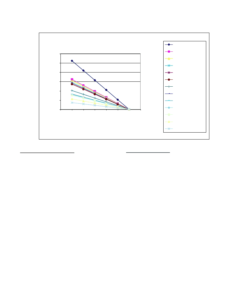
Power Dissipation vs. Ambient Temperature
Absolute Minimum PCB footprint
0.00
0.50
1.00
1.50
2.00
2.50
3.00
0
25
50
75
100
125
175
T_ambient(°C)
P
D2-Pak **
D-Pak **
mid-can DirectFET **
SOT-223
small-can DirectFET **
SO-8
SO-8 (Dual)
TSSOP8
TSOP6 (Single)
u-6
u-8
TSOP6 (Dual)
u-3
Figure 4:
Absolute Min Power Dissipation (T ambient)
Section III: Attachment to board:
Most designers and technicians in the electronic industry are
familiar with printed circuits that are provided with holes to
support leaded components during the soldering process.
Surface mount components on the other hand are by
definition leadless and rely on the strength of the solder joint
alone for mechanical as well as electrical connection. Many
PCB assemblies require the mounting of devices on both
sides of the board. The reflow process is typically performed
once. Both sides of the board are pasted at the same time.
Components are then placed on the topside only. An
adhesive is then applied to the topside to hold the
components in place. The board is then inverted 180
degrees and the second side is populated with components.
At that point the populated board is ready for the thermal
process that will melt the solder paste and attach the
components to the board. After the mounting process is
complete the adhesive serves no further purpose.
The adhesives used must provide sufficient tenacity to
prevent component movement during handling and soldering.
At the same time, the adhesive should provide a bond that
can be broken with minimal disturbance to the populated
board in order to replace incorrect components before
soldering. It must also be capable of maintaining adhesion
during the preheat cycle and it should not become a deterrent
to solder flow during the reflow or wave soldering process.
Typical adhesives of this type are made from non-activated
resins (R), which can be used in forming gas atmosphere to
reduce oxides. Some are mildly activated resin (RMA), which
can be used in normal factory environment. The activation in
this case is used to reduce
small amounts of oxidation of the
solderable surfaces and the solder particles in the paste.
相關PDF資料 |
PDF描述 |
|---|---|
| AN-CC1002 | Design Considerations for ISD1700 Family |
| AN013 | JT 128C 128#22D SKT RECP |
| AN1025 | Converting A 5.0V Supply Rail To A Regulated 3.0V |
| AN1034 | Analog Switch and Multiplexer Applications |
| AN1042 | High Fidelity Switching Audio Amplifiers Using TMOS Power MOSFETs |
相關代理商/技術參數(shù) |
參數(shù)描述 |
|---|---|
| AN-995A | 制造商:未知廠家 制造商全稱:未知廠家 功能描述:Electronic Ballasts Using the Cost-Saving IR215X Drivers(153.99 k) |
| AN-996 | 制造商:FAIRCHILD 制造商全稱:Fairchild Semiconductor 功能描述:Using the Fairchild FST Bus Switch as a 5V to 3V Translator |
| AN9C10A | 制造商: 功能描述: 制造商:undefined 功能描述: |
| AN9D | 制造商:PANASONIC 制造商全稱:Panasonic Semiconductor 功能描述:Analog master slice IC series |
| AN9DA00 | 制造商:PANASONIC 制造商全稱:Panasonic Semiconductor 功能描述:Analog master slice IC series |
發(fā)布緊急采購,3分鐘左右您將得到回復。