- 您現(xiàn)在的位置:買賣IC網(wǎng) > PDF目錄378403 > AN-902 (National Semiconductor Corporation) Twisted Pair FDDI Magnetics Overview and Recommendations PDF資料下載
參數(shù)資料
| 型號: | AN-902 |
| 廠商: | National Semiconductor Corporation |
| 英文描述: | Twisted Pair FDDI Magnetics Overview and Recommendations |
| 中文描述: | 雙絞線FDDI的磁性分析和建議 |
| 文件頁數(shù): | 4/10頁 |
| 文件大小: | 209K |
| 代理商: | AN-902 |
6.8
Conducted Power Spectrum
The conducted Power Spectrum offers a convenient meth-
od of understanding and comparing the differential power
spectrum of a given set of magnetics. Due to the similarities
between the conducted spectra of each of the magnetics
tested herein, only typical measurements are presented. Of
specific interest are the differences between the binary and
MLT-3 encoded conducted power spectrum for scrambled
line code. Although MLT-3 suffers from 6 dB lower noise
immunity than binary given equal transmit amplitudes,
MLT-3 does exhibit an improvement in the reduction of dif-
ferential conducted power at key frequencies.
Conducted Power
(dBm)
Binary
MLT-3
@
31.25 MHz
b
47.0
b
53.0
@
62.50 MHz
b
53.0
b
62.0
(Refer to Figures 6 and 7.)
6.9
Radiated Emissions
Currently, no data is provided for this parameter. However,
preliminary data will be available soon. Please contact Na-
tional Semiconductor for information pertaining to the Radi-
ated Emissions of suggested PMD implementations.
6.10
EMI Susceptibility
Currently, no data is provided for this parameter. However,
preliminary data will be available soon. Please contact Na-
tional Semiconductor for information pertaining to the EMI
Susceptibility of suggested PMD implementations.
7.0
ADDITIONAL PARAMETERS
Ultimately, the most important performance factor of Twist-
ed Pair FDDI signaling is long term, error free data transmis-
sion. To ensure that each of the four magnetics solutions
tested herein will support error free transmission, 16 sepa-
rate bit error rate (BER) tests were performed. Each of the
four magnetics were tested against themselves and each
other at both the transmit and receive ends of the transmis-
sion system. Specifically, each test was performed using
130 meters of Category 5 cable with scrambled code set at
2.0V peak-to-peak differential transmit voltage. These tests
were performed for both Binary and MLT-3 signal encoding.
Each of the 16 BER tests passed proving acceptable inter-
operability in terms of the magnetics to the TP-PMD stan-
dard BER limit of
k
10E-12.
Several additional electrical parameters exist for each of the
magnetics solutions presented herein. Although these pa-
rameters are not included in this analysis, they are nonethe-
less important and may help to further inform the system
designer regarding performance. Each of the magnetics
vendors publish a list of these specifications, tolerances and
test conditions included where applicable, to accompany
their solutions. It is best to refer to these figures for a more
comprehensive understanding of performance. Some of the
standard parameters associated with magnetics include:
D Turns Ratio
D OCL (open circuit inductance)
D LL (leakage inductance)
D Cw/w (interwinding capacitance)
D DCR (DC resistance)
D HI POT (high voltage tolerance)
D CMR (common mode rejection)
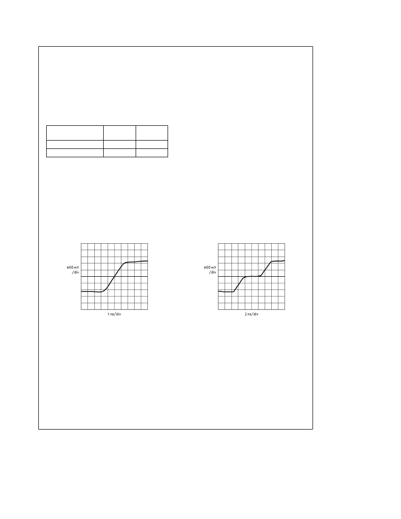
TL/F/11894–1
FIGURE 1. Typical Binary Transitions
TL/F/11894–2
FIGURE 2. Typical MLT-3 Transitions
4
相關(guān)PDF資料 |
PDF描述 |
|---|---|
| AN-90 | 74C Family Characteristics |
| AN-994-1 | MAXIMIZING THE EFFECTIVENESS OF YOUR SMD ASSEMBLIES |
| AN-CC1002 | Design Considerations for ISD1700 Family |
| AN013 | JT 128C 128#22D SKT RECP |
| AN1025 | Converting A 5.0V Supply Rail To A Regulated 3.0V |
相關(guān)代理商/技術(shù)參數(shù) |
參數(shù)描述 |
|---|---|
| AN-9032 | 制造商:FAIRCHILD 制造商全稱:Fairchild Semiconductor 功能描述:SPM? TEST BOARD for use in Isolated Inverter GND |
| AN-9033 | 制造商:FAIRCHILD 制造商全稱:Fairchild Semiconductor 功能描述:SPM? TEST BOARD for use in Isolated Inverter GND |
| AN-9037 | 制造商:FAIRCHILD 制造商全稱:Fairchild Semiconductor 功能描述:8x8 MLP DriverMOS Packaging |
| AN904 | 制造商:STMICROELECTRONICS 制造商全稱:STMicroelectronics 功能描述:MAGNETIC AMPLIFIER WITH LPR30 CONTROLLER |
| AN-9040 | 制造商:FAIRCHILD 制造商全稱:Fairchild Semiconductor 功能描述:Power33 Packaging |
發(fā)布緊急采購,3分鐘左右您將得到回復。