- 您現(xiàn)在的位置:買賣IC網(wǎng) > PDF目錄166131 > AK4532-E2 SPECIALTY CONSUMER CIRCUIT, PDSO24 PDF資料下載
參數(shù)資料
| 型號: | AK4532-E2 |
| 元件分類: | 消費家電 |
| 英文描述: | SPECIALTY CONSUMER CIRCUIT, PDSO24 |
| 封裝: | 0.65 MM PITCH, PLASTIC, VSOP-24 |
| 文件頁數(shù): | 4/17頁 |
| 文件大小: | 239K |
| 代理商: | AK4532-E2 |

ASAHI KASEI
[AK4532]
0178-E-02
12
2004/12
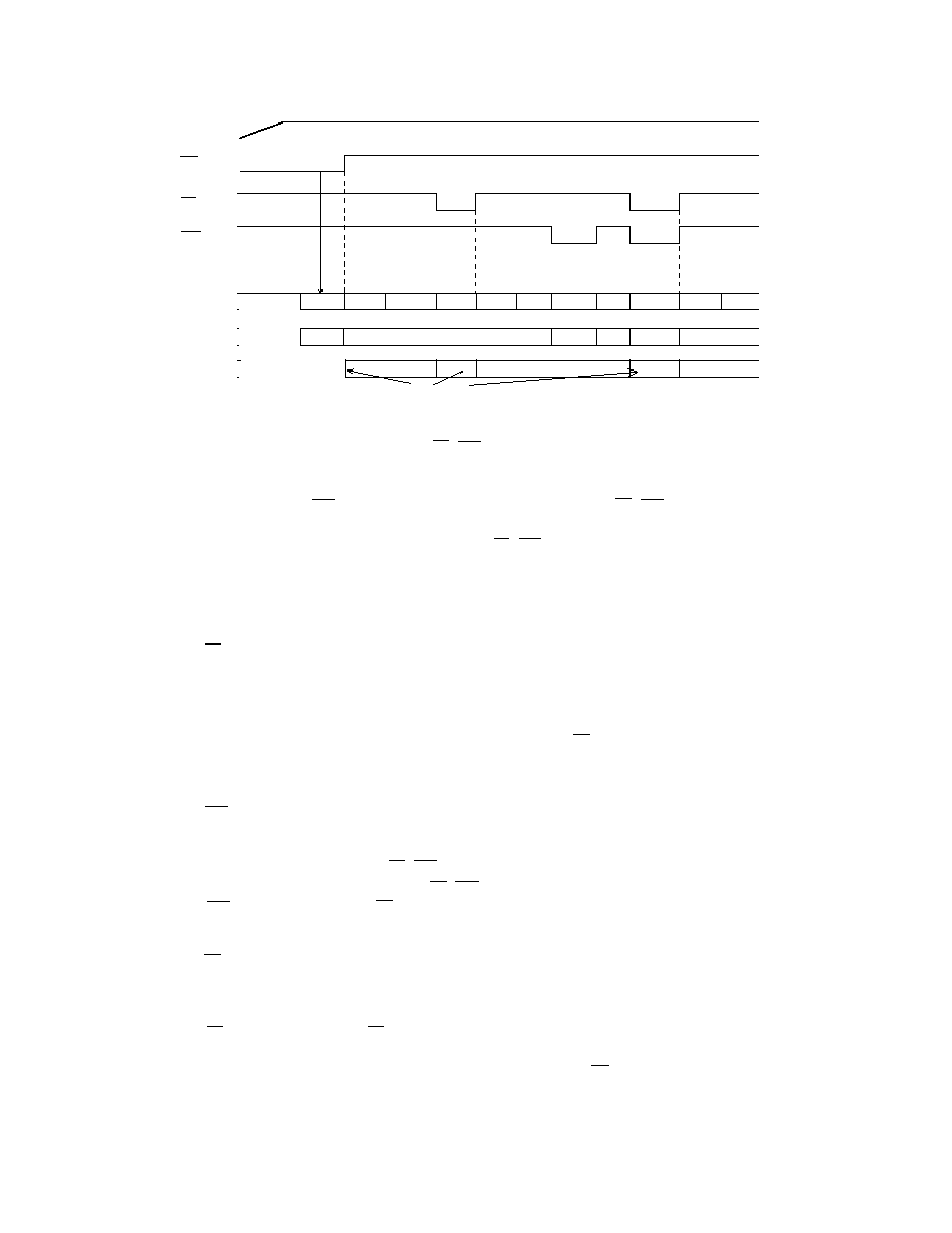
4. Explanation of each sequence
4.1. Reset & Power down
INIT1
INITA
Normal
PD
Normal
INIT2
Normal PD+INIT2
Normal
Inhibit(1)
Inhibit(2)
Inhibit(2
Power Supply
PD pin
PD(register)
RST(register)
Internal State
Write to register
External clock
MCLK,LRCK,SCLK
The clocks may be stopped.
INITA
INIT1:
Initializing all registers. The AK4532 exists in the power down state.
INIT2:
Initializing all registers except PD
, RST registers.
INITA:
Initializing the analog section. Initializing period is 516/fs.
PD:
Power down state. All analog outputs are floating.
In case of RST register = “0”, initializing all registers except PD
, RST registers.
Inhibit(1): Inhibits writing to all registers.
Inhibit(2): Inhibits writing to all registers except for PD , RST registers.
The AK4532 operates with the external clocks(MCLK, LRCK, SCLK) during initializing the
analog section.
Figure 1. Reset & Power Down Sequence
4.2. PD pin operation
“H”: Normal operation
“L”: Initializing mode 1(INIT1 in Figure 1)
Initializing all registers.
Inhibits writing to all registers.
The initialization of the analog section starts at rising edge of PD pin.
SDO pin stays “L” during the initializing periods of 516/fs.
Going into power down state.
4.3. RST register operation
“1”: Normal operation
“0”: Initializing mode 2(INIT2 in Figure 1)
Initializing all registers except PD , RST registers.
Inhibits writing to all registers except PD , RST registers.
RST register goes “1” when PD pin goes “L”.
The analog section is not initialized.
4.4. PD register operation
“1”: Normal operation
“0”: Power down
The contents of all registers are held.
PD resister goes “1” when PD pin goes “L”.
All analog outputs(LOUT, ROUT) go floating.
The initialization of the analog section starts at the rising edge of PD resister.
SDO pin stays “L” during the initializing period of 516/fs.
4.5. SDO output pin operation
相關(guān)PDF資料 |
PDF描述 |
|---|---|
| AK4532P-E2 | SPECIALTY CONSUMER CIRCUIT, PDSO24 |
| AK4552 | 3V 96KHZ 24BIT CODEC |
| AK4552VT | 3V 96KHZ 24BIT CODEC |
| AK4571 | USB I/F Audio CODEC |
| AK4571VQ | USB I/F Audio CODEC |
相關(guān)代理商/技術(shù)參數(shù) |
參數(shù)描述 |
|---|---|
| AK4533 | 制造商:AKM 制造商全稱:AKM 功能描述:Audio Codec with Touch Screen Controller |
| AK4534 | 制造商:AKM 制造商全稱:AKM 功能描述:16Bit CODEC with MIC/HP/SPK-AMP |
| AK4534VN | 制造商:AKM 制造商全稱:AKM 功能描述:16Bit CODEC with MIC/HP/SPK-AMP |
| AK4534VQ | 功能描述:IC CODEC 16BIT MIC/HP/SPK-AMP 制造商:akm semiconductor inc. 系列:* 零件狀態(tài):上次購買時間 標(biāo)準(zhǔn)包裝:1,000 |
| AK4536 | 制造商:AKM 制造商全稱:AKM 功能描述:16-Bit Mono CODEC with ALC & MIC/SPK-AMP |
發(fā)布緊急采購,3分鐘左右您將得到回復(fù)。