- 您現(xiàn)在的位置:買賣IC網(wǎng) > PDF目錄294979 > AEH10G24-N 1-OUTPUT 25 W DC-DC REG PWR SUPPLY MODULE PDF資料下載
參數(shù)資料
| 型號(hào): | AEH10G24-N |
| 元件分類: | 電源模塊 |
| 英文描述: | 1-OUTPUT 25 W DC-DC REG PWR SUPPLY MODULE |
| 文件頁(yè)數(shù): | 21/38頁(yè) |
| 文件大小: | 517K |
| 代理商: | AEH10G24-N |
第1頁(yè)第2頁(yè)第3頁(yè)第4頁(yè)第5頁(yè)第6頁(yè)第7頁(yè)第8頁(yè)第9頁(yè)第10頁(yè)第11頁(yè)第12頁(yè)第13頁(yè)第14頁(yè)第15頁(yè)第16頁(yè)第17頁(yè)第18頁(yè)第19頁(yè)第20頁(yè)當(dāng)前第21頁(yè)第22頁(yè)第23頁(yè)第24頁(yè)第25頁(yè)第26頁(yè)第27頁(yè)第28頁(yè)第29頁(yè)第30頁(yè)第31頁(yè)第32頁(yè)第33頁(yè)第34頁(yè)第35頁(yè)第36頁(yè)第37頁(yè)第38頁(yè)

A
A
A E
E
E H
H
H 2
2
2 4
4
4 V
V
V IIIIn
n
n p
p
p u
u
u tttt H
H
H a
a
a llllffff--B
B
B rrrriiiic
c
c k
k
k S
S
S e
e
e rrrriiiie
e
e s
s
s P
P
P o
o
o w
w
w e
e
e rrrr C
C
C o
o
o n
n
n v
v
v e
e
e rrrrtttte
e
e rrrrs
s
2
2 ....5
5
5 V
V
V,,,, 3
3
3 ....3
3
3 V
V
V,,,, 5
5
5 V
V
V S
S
S iiiin
n
n g
g
g lllle
e
e O
O
O u
u
u ttttp
p
p u
u
u tttt,,,, 5
5
5 0
0
0 --1
1
1 5
5
5 0
0
0 W
W
-28-
USA
Europe
Asia
TEL:
1-760-930-4600
44-(0)1384-842-211
852-2437-9662
FAX:
1-760-930-0698
44-(0)1384-843-355
852-2402-4426
www.astec.com
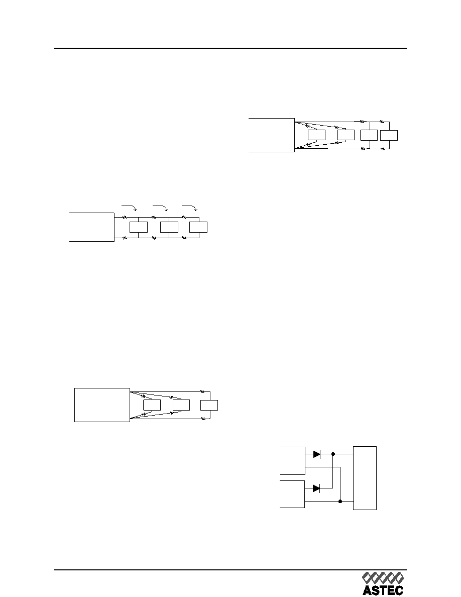
Parallel Power Distribution
Figure 20 shows a typical parallel power distri-
bution design. Such designs, sometimes called
daisy chains, can be used for very low output
currents, but are not normally recommended.
The voltage across loads far from the source
can vary greatly depending on the IR drops
along the leads and changes in the loads clos-
er to the source. Dynamic load conditions
increase the potential problems.
Radial Power Distribution
Radial power distribution is the preferred
method of providing power to the load. Figure
21 shows how individual loads are connected
directly to the power source. This arrangement
requires additional power leads, but it avoids
the voltage variation problems associated with
the parallel power distribution technique.
Mixed Distribution
In the real world a combination of parallel and
radial power distribution is often used. Dynamic
and high current loads are connected using a
radial design, while static and low current loads
can be connected in parallel. This combined
approach minimizes the drawbacks of a parallel
design when a purely radial design is not feasi-
ble.
Redundant Operation
A common requirement in high reliability sys-
tems is to provide redundant power supplies.
The easiest way to do this is to place two con-
verters in parallel, providing fault tolerance but
not load sharing. Oring diodes should be used
to ensure that failure of one converter will not
cause failure of the second. Figure 23 shows
such an arrangement. Upon application of
power, one of the converters will provide a
slightly higher output voltage and will support
the full load demand. The second converter will
see a zero load condition and will “idle”. If the
first converter should fail, the second converter
will support the full load. When designing
redundant converter circuits, Shottky diodes
should be used to minimize the forward voltage
drop. The voltage drop across the Shottky
diodes must also be considered when deter-
mining load voltage requirements.
Load 1
Load 2
Load 3
+Vout
-Vout
RL1
RL2
RL3
RG1
RG2
RG3
RL = Lead Resistance
RG = Ground Lead Resistance
Fig.21 Radial Power Distribution
Load 1
Load 2
Load 3
+Vout
-Vout
RL1
RL2
RL3
RG1
RG2
RG3
I1 + I2 + I3
I2 + I3
I3
RL = Lead Resistance
RG = Ground Lead Resistance
Fig.20 Parallel Power Distribution
Load 1
Load 2
Load 3
+Vout
-Vout
RL1
RL2
RL3
RG1
RG2
RG3
RL = Lead Resistance
RG = Ground Lead Resistance
Load 4
RL4
RG4
Fig.22 Mixed Power Distribution
+Vout
-Vout
+Vout
-Vout
Load
Fig.23 Redundant Operation
相關(guān)PDF資料 |
PDF描述 |
|---|---|
| AEH30A24-6 | 1-OUTPUT DC-DC REG PWR SUPPLY MODULE |
| AEUFB-BR1 | INTERCONNECTION DEVICE |
| BANFA-BS1 | INTERCONNECTION DEVICE |
| AEV110122 | POWER/SIGNAL RELAY, SPST, MOMENTARY, 0.013A (COIL), 12VDC (COIL), 1400mW (COIL), 10A (CONTACT), 400VDC (CONTACT), PANEL MOUNT |
| AEV110242 | POWER/SIGNAL RELAY, SPST, MOMENTARY, 0.052A (COIL), 24VDC (COIL), 1400mW (COIL), 10A (CONTACT), 400VDC (CONTACT), PANEL MOUNT |
相關(guān)代理商/技術(shù)參數(shù) |
參數(shù)描述 |
|---|---|
| AEH10G48 | 功能描述:DC/DC轉(zhuǎn)換器 CONV DC-DC 50W 48VIN RoHS:否 制造商:Murata 產(chǎn)品: 輸出功率: 輸入電壓范圍:3.6 V to 5.5 V 輸入電壓(標(biāo)稱): 輸出端數(shù)量:1 輸出電壓(通道 1):3.3 V 輸出電流(通道 1):600 mA 輸出電壓(通道 2): 輸出電流(通道 2): 安裝風(fēng)格:SMD/SMT 封裝 / 箱體尺寸: |
| AEH10G48N | 功能描述:DC/DC轉(zhuǎn)換器 CONV DC-DC 50W 48VIN RoHS:否 制造商:Murata 產(chǎn)品: 輸出功率: 輸入電壓范圍:3.6 V to 5.5 V 輸入電壓(標(biāo)稱): 輸出端數(shù)量:1 輸出電壓(通道 1):3.3 V 輸出電流(通道 1):600 mA 輸出電壓(通道 2): 輸出電流(通道 2): 安裝風(fēng)格:SMD/SMT 封裝 / 箱體尺寸: |
| AEH130PD01 | 制造商:XPPOWER 制造商全稱:XP Power Limited 功能描述:AC-DC Power Supplies |
| AEH130PD02 | 制造商:XPPOWER 制造商全稱:XP Power Limited 功能描述:AC-DC Power Supplies |
| AEH130PD03 | 制造商:XPPOWER 制造商全稱:XP Power Limited 功能描述:AC-DC Power Supplies |
發(fā)布緊急采購(gòu),3分鐘左右您將得到回復(fù)。