- 您現(xiàn)在的位置:買賣IC網(wǎng) > PDF目錄294979 > AEH10G24-N8 1-OUTPUT 25 W DC-DC REG PWR SUPPLY MODULE PDF資料下載
參數(shù)資料
| 型號(hào): | AEH10G24-N8 |
| 元件分類: | 電源模塊 |
| 英文描述: | 1-OUTPUT 25 W DC-DC REG PWR SUPPLY MODULE |
| 文件頁(yè)數(shù): | 27/38頁(yè) |
| 文件大?。?/td> | 517K |
| 代理商: | AEH10G24-N8 |
第1頁(yè)第2頁(yè)第3頁(yè)第4頁(yè)第5頁(yè)第6頁(yè)第7頁(yè)第8頁(yè)第9頁(yè)第10頁(yè)第11頁(yè)第12頁(yè)第13頁(yè)第14頁(yè)第15頁(yè)第16頁(yè)第17頁(yè)第18頁(yè)第19頁(yè)第20頁(yè)第21頁(yè)第22頁(yè)第23頁(yè)第24頁(yè)第25頁(yè)第26頁(yè)當(dāng)前第27頁(yè)第28頁(yè)第29頁(yè)第30頁(yè)第31頁(yè)第32頁(yè)第33頁(yè)第34頁(yè)第35頁(yè)第36頁(yè)第37頁(yè)第38頁(yè)

A
A
A E
E
E H
H
H 2
2
2 4
4
4 V
V
V IIIIn
n
n p
p
p u
u
u tttt H
H
H a
a
a llllffff--B
B
B rrrriiiic
c
c k
k
k S
S
S e
e
e rrrriiiie
e
e s
s
s P
P
P o
o
o w
w
w e
e
e rrrr C
C
C o
o
o n
n
n v
v
v e
e
e rrrrtttte
e
e rrrrs
s
2
2 ....5
5
5 V
V
V,,,, 3
3
3 ....3
3
3 V
V
V,,,, 5
5
5 V
V
V S
S
S iiiin
n
n g
g
g lllle
e
e O
O
O u
u
u ttttp
p
p u
u
u tttt,,,, 5
5
5 0
0
0 --1
1
1 5
5
5 0
0
0 W
W
-33-
USA
Europe
Asia
TEL:
1-760-930-4600
44-(0)1384-842-211
852-2437-9662
FAX:
1-760-930-0698
44-(0)1384-843-355
852-2402-4426
www.astec.com
or
thermal pads available from Astec) can
result in a case-heatsink thermal impedance
around 0.1°C/W.
Natural Convection with Heat Sink
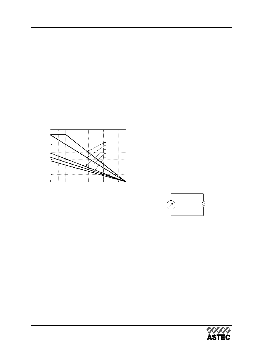
The power derating for a module with the heat
sinks ( shown as figure 25 to figure 30) in nat-
ural convection is shown in figure 35. In this
test, natural convection generates airflow about
0.05 m/s to 0.1 m/s ( 10ft./min to 20ft./min ).
Figure 37 can be used for heat-sink selection in
natural convection environment.
Example 3. How to select a heat sink?
What heat sink would be appropriate for a
AEH20A24N in a natural convection environ-
ment at nominal line, 2/3 load, and maximum
ambient temperature of 40°C?
Determine PD ( referenced Fig.30 ) with con-
dition:
Vin = 24 V
IO = 2/3 (20) = 13 A
TA = 40 °C
Get: PD = 10.5 W
Determine Heat Sink ( Fig.37 ):
no heat sink allows up to TA = 30 °C
1/4 in. allows up to TA = 40 ° C
Basic Thermal Model
There is another approach to analyze module
thermal performance, to model the overall ther-
mal resistance of the module. This presentation
method is especially useful when considering
heat sinks. The following equation can be used
to calculate the total thermal resistance .
RCA =
TC, max / PD
Where RCA is the module thermal resistance;
TC, max is the maximum case temperature
rise;
PD is the module power dissipation.
In this model, PD,
TC, max, and RCA are equals
to current flow, voltage drop, and electrical
resistance, respectively, in Ohm's law, as
shown in Figure 38. Also,
TC, max is defined as
the difference between the module case tem-
perature (TC) and the inlet ambient temperature
(TA).
TC, max = TC TA
Where TC is the module case temperature,
TA is the inlet ambient temperature.
For AEH 24Vin Series 50W to 150W convert-
ers, the module's thermal resistance values
versus air velocity have been determined
experimentally and shown in figure 39. The
highest values on each curve represents the
point of natural convection.
Figure 39 is used for determining thermal per-
formance under various conditions of airflow
and heat sink configurations.
0
10
203040
90 100
0
20
25
30
35
LOCAL AMBIENT TEMPERATURE, TA (°C)
POWER
DISSIPATION,
P
D
15
10
5
50
60
70
80
1 1/2 in.
1 in.
1/2 in.
1/4 in.
NONE
Fig.37 Heat Sink Power Derating Curves,
Natural Convection
BMPM
PD
= BMPM
THERMAL
RESISTANCE
Fig.38 Basic Thermal Resistance Model
相關(guān)PDF資料 |
PDF描述 |
|---|---|
| AEH10G24-N | 1-OUTPUT 25 W DC-DC REG PWR SUPPLY MODULE |
| AEH30A24-6 | 1-OUTPUT DC-DC REG PWR SUPPLY MODULE |
| AEUFB-BR1 | INTERCONNECTION DEVICE |
| BANFA-BS1 | INTERCONNECTION DEVICE |
| AEV110122 | POWER/SIGNAL RELAY, SPST, MOMENTARY, 0.013A (COIL), 12VDC (COIL), 1400mW (COIL), 10A (CONTACT), 400VDC (CONTACT), PANEL MOUNT |
相關(guān)代理商/技術(shù)參數(shù) |
參數(shù)描述 |
|---|---|
| AEH10G48 | 功能描述:DC/DC轉(zhuǎn)換器 CONV DC-DC 50W 48VIN RoHS:否 制造商:Murata 產(chǎn)品: 輸出功率: 輸入電壓范圍:3.6 V to 5.5 V 輸入電壓(標(biāo)稱): 輸出端數(shù)量:1 輸出電壓(通道 1):3.3 V 輸出電流(通道 1):600 mA 輸出電壓(通道 2): 輸出電流(通道 2): 安裝風(fēng)格:SMD/SMT 封裝 / 箱體尺寸: |
| AEH10G48N | 功能描述:DC/DC轉(zhuǎn)換器 CONV DC-DC 50W 48VIN RoHS:否 制造商:Murata 產(chǎn)品: 輸出功率: 輸入電壓范圍:3.6 V to 5.5 V 輸入電壓(標(biāo)稱): 輸出端數(shù)量:1 輸出電壓(通道 1):3.3 V 輸出電流(通道 1):600 mA 輸出電壓(通道 2): 輸出電流(通道 2): 安裝風(fēng)格:SMD/SMT 封裝 / 箱體尺寸: |
| AEH130PD01 | 制造商:XPPOWER 制造商全稱:XP Power Limited 功能描述:AC-DC Power Supplies |
| AEH130PD02 | 制造商:XPPOWER 制造商全稱:XP Power Limited 功能描述:AC-DC Power Supplies |
| AEH130PD03 | 制造商:XPPOWER 制造商全稱:XP Power Limited 功能描述:AC-DC Power Supplies |
發(fā)布緊急采購(gòu),3分鐘左右您將得到回復(fù)。