- 您現(xiàn)在的位置:買賣IC網(wǎng) > PDF目錄375225 > AC12EGML Thyristor Product Catalog PDF資料下載
參數(shù)資料
| 型號: | AC12EGML |
| 英文描述: | Thyristor Product Catalog |
| 中文描述: | 晶閘管產(chǎn)品目錄 |
| 文件頁數(shù): | 164/224頁 |
| 文件大小: | 2697K |
| 代理商: | AC12EGML |
第1頁第2頁第3頁第4頁第5頁第6頁第7頁第8頁第9頁第10頁第11頁第12頁第13頁第14頁第15頁第16頁第17頁第18頁第19頁第20頁第21頁第22頁第23頁第24頁第25頁第26頁第27頁第28頁第29頁第30頁第31頁第32頁第33頁第34頁第35頁第36頁第37頁第38頁第39頁第40頁第41頁第42頁第43頁第44頁第45頁第46頁第47頁第48頁第49頁第50頁第51頁第52頁第53頁第54頁第55頁第56頁第57頁第58頁第59頁第60頁第61頁第62頁第63頁第64頁第65頁第66頁第67頁第68頁第69頁第70頁第71頁第72頁第73頁第74頁第75頁第76頁第77頁第78頁第79頁第80頁第81頁第82頁第83頁第84頁第85頁第86頁第87頁第88頁第89頁第90頁第91頁第92頁第93頁第94頁第95頁第96頁第97頁第98頁第99頁第100頁第101頁第102頁第103頁第104頁第105頁第106頁第107頁第108頁第109頁第110頁第111頁第112頁第113頁第114頁第115頁第116頁第117頁第118頁第119頁第120頁第121頁第122頁第123頁第124頁第125頁第126頁第127頁第128頁第129頁第130頁第131頁第132頁第133頁第134頁第135頁第136頁第137頁第138頁第139頁第140頁第141頁第142頁第143頁第144頁第145頁第146頁第147頁第148頁第149頁第150頁第151頁第152頁第153頁第154頁第155頁第156頁第157頁第158頁第159頁第160頁第161頁第162頁第163頁當前第164頁第165頁第166頁第167頁第168頁第169頁第170頁第171頁第172頁第173頁第174頁第175頁第176頁第177頁第178頁第179頁第180頁第181頁第182頁第183頁第184頁第185頁第186頁第187頁第188頁第189頁第190頁第191頁第192頁第193頁第194頁第195頁第196頁第197頁第198頁第199頁第200頁第201頁第202頁第203頁第204頁第205頁第206頁第207頁第208頁第209頁第210頁第211頁第212頁第213頁第214頁第215頁第216頁第217頁第218頁第219頁第220頁第221頁第222頁第223頁第224頁
AN1006
Application Notes
http://www.teccor.com
+1 972-580-7777
AN1006 - 12
2002 Teccor Electronics
Thyristor Product Catalog
7. Set
Terminal Selector
to
Emitter Grounded-Open Base
.
Procedure 5: V
BO (Positive and Negative)
To measure the V
BO (Positive and Negative)
parameter:
1. Set
Left-Right Terminal Jack Selector
to correspond with
the location of the test fixture.
2. Set
Variable Collector Supply Voltage
to
55 V
(
65 V
on
370) and apply voltage to the device under test (D.U.T.)
using the
Left Hand Selector Switch.
The peak voltage at
which current begins to flow is the V
BO
value.
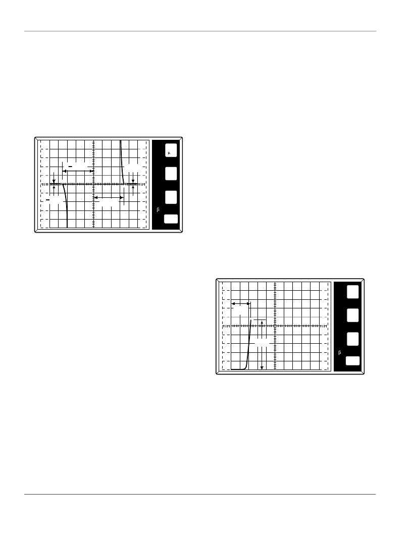
(Figure AN1006.19)
Figure AN1006.19 (+)V
BO
= 35 V; (-)V
BO
= 36 V; (±)I
BO
< 10 A
Procedure 6: I
BO (Positive and Negative)
To measure the I
BO (Positive and Negative)
parameter, at the V
BO
point,
measure the amount of device current just before the device
reaches the breakover point. The measured current at this point
is the I
BO
value.
Note: If I
is less than 10 μA, the current cannot readily be seen
on curve tracer.
Procedure 7:
V
BO (Voltage Breakover Symmetry)
To measure the
V
BO (Voltage Breakover Symmetry)
parameter:
1. Measure positive and negative V
BO
values per Procedure 5.
2. Subtract the absolute value of V
BO
(-) from V
BO
(+).
The absolute value of the result is:
V
BO
= [ I+V
BO
I - I -V
BO
I ]
Procedure 8: V
TM (Forward and Reverse)
To test V
TM
, the
Quadrac
must be connected the same as when
testing V
BO
, I
BO
, and
V
BO
.
To connect the
Quadrac
:
1. Connect
MT1
to
Emitter Terminal
(E).
2. Connect
MT2
to
Collector Terminal
(C).
3. Connect
Trigger Terminal
to
MT2 Terminal
through a 10
resistor.
Note the following:
Due to the excessive amount of power that can be generated in
this test, only parts with an I
T(RMS)
rating of 8 A or less should be
tested on standard curve tracer. If testing devices above 8 A, a
Tektronix model 176 high-current module is required.
A Kelvin test fixture is required for this test. If a Kelvin fixture is
not used, an error in measurement of V
TM
will result due to volt-
age drop in fixture. If a Kelvin fixture is not available,
Figure AN1006.3 shows necessary information to wire a test
fixture with Kelvin connections.
To measure the V
TM (Forward and Reverse)
parameter:
1. Set
Terminal Selector
to
Emitter Grounded-Open Base
.
2. Set
Max Peak Volts
to
75 V
. (
80 V
on 370)
3. Set
Mode
to
Norm
.
4. Set
Horizontal
knob to
0.5 V/DIV
.
5. Set
Power Dissipation
to
220 watts
(
100 watts
on a 577).
6. Set
Vertical
knob to a sufficient setting to allow the viewing
of 1.4 times the I
T(RMS)
rating of the device I
T(peak)
on the CRT.
Procedure 9: V
TM(Forward)
To measure the V
TM (Forward)
parameter:
1. Set
Polarity
to (+).
2. Set
Left-Right Terminal Jack Selector
to correspond with
the location of the test fixture.
3. Increase
Variable Collector Supply Voltage
until current
reaches rated I
T(peak)
, which is 1.4 times the I
T(RMS)
rating of
the triac under test.
Note: Model 370 current is limited to 10 A.
WARNING: Limit test time to 15 seconds maximum.
4. To measure V
TM
, follow along horizontal scale to the point
where the trace crosses the I
T(peak)
value. This horizontal dis-
tance is the V
TM
value. (Figure AN1006.20)
Figure AN1006.20 V
TM (Forward)
= 1.1 V at I
PK
= 5.6 A
Procedure 10: V
TM(Reverse)
To measure the V
TM (Reverse)
parameter:
1. Set
Polarity
to (–).
2. Set
Left-Right Terminal Jack Selector
to correspond with
the location of the test fixture.
3. Increase
Variable Collector Supply Voltage
until current
reaches rated I
T(peak)
.
4. Measure V
TM(Reverse)
the same as in Procedure 8. (Read mea-
surements from upper right corner of screen).
50
A
10
V
PER
V
E
R
T
DIV
PER
H
O
R
I
Z
DIV
PER
S
T
E
P
()k
DIV
9m
PER
DIV
VBO
IBO
+VBO
+IBO
500
mV
PER
V
E
R
T
DIV
PER
H
O
R
I
Z
DIV
PER
S
T
E
P
IPK
VTM
1
A
()k
DIV
9m
PER
DIV
相關PDF資料 |
PDF描述 |
|---|---|
| AC12ESM | Thyristor Product Catalog |
| AC12FGML | Thyristor Product Catalog |
| AC12FSM | Thyristor Product Catalog |
| AC16BGM | Thyristor Product Catalog |
| AC16BSM | Thyristor Product Catalog |
相關代理商/技術參數(shù) |
參數(shù)描述 |
|---|---|
| AC12ESM | 制造商:TECCOR 制造商全稱:TECCOR 功能描述:Thyristor Product Catalog |
| AC12FGM | 制造商:NEC 制造商全稱:NEC 功能描述:12A MOLD TRIAC |
| AC12FGM(AZ) | 制造商:Renesas Electronics Corporation 功能描述: |
| AC12FGML | 制造商:TECCOR 制造商全稱:TECCOR 功能描述:Thyristor Product Catalog |
| AC12FSM | 制造商:TECCOR 制造商全稱:TECCOR 功能描述:Thyristor Product Catalog |
發(fā)布緊急采購,3分鐘左右您將得到回復。