- 您現(xiàn)在的位置:買賣IC網(wǎng) > PDF目錄362047 > ABT22V10A7 (NXP Semiconductors N.V.) 5V high-speed universal PLD device with live insertion capability(具有活插入能力的5V高速通用PLD器件) PDF資料下載
參數(shù)資料
| 型號: | ABT22V10A7 |
| 廠商: | NXP Semiconductors N.V. |
| 英文描述: | 5V high-speed universal PLD device with live insertion capability(具有活插入能力的5V高速通用PLD器件) |
| 中文描述: | 5V的高速插入活通用PLD器件的能力(具有活插入能力的5V的高速通用可編程邏輯器件) |
| 文件頁數(shù): | 4/18頁 |
| 文件大小: | 302K |
| 代理商: | ABT22V10A7 |
Philips Semiconductors
Product specification
ABT22V10A5, A7
5V high-speed universal PLD device
with live insertion capability
1996 Dec 16
4
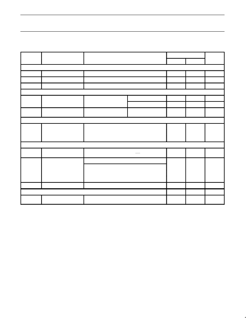
DC ELECTRICAL CHARACTERISTICS
Over operating ranges.
SYMBOL
PARAMETER
TEST CONDITIONS
1
LIMITS
UNIT
MIN
MAX
Input voltage
V
IL
Low
V
CC
= MIN
0.8
V
V
IH
High
V
CC
= MAX
2.0
V
V
I
Clamp
V
CC
= MIN, I
IN
= –18mA
–1.2
V
Output voltage
V
OH
High-level output voltage
V
I
IH
or V
IL
I
OH
= –32mA
2.0
V
V
CC
= MIN
I
OH
= –16mA
2.4
V
V
OL
Low-level output voltage
V
CC
= MIN
V
I
IH
or V
IL
I
OL
= 48mA
0.5
V
Input current
I
IL
Low
V
CC
= MAX, V
IN
= 0.4V
–10
μ
A
I
IH
High
V
CC
= MAX, V
IN
= 2.7V
10
μ
A
I
I
Max input current
V
CC
= MAX, V
IN
= 5.5V
20
μ
A
Output current
I
PU/PD
Power-up/down 3-State
output current
4
V
CC
<2.1V; V
O
= 0.5V to V
;
V
I
CC
; OE/OE = X
50
μ
A
V
CC
= MAX
I
OZH
Output leakage
2
V
IN
= V
IL
or V
IH
, V
OUT
= 2.7V
20
μ
A
I
OZL
Output leakage
2
V
IN
= V
IL
or V
IH
, V
OUT
=0.4V
–20
μ
A
I
SC
Short circuit
3
V
OUT
= 0.5V
–30
–220
mA
I
CC
V
CC
supply current
V
CC
= MAX, Outputs enabled, V
I
= V
CC
or GND; I
O
= 0
200
mA
Ground Bounce
TYP
MAX
UNIT
V
OLP
Minimum dynamic V
OH5
V
= MAX, 25
°
C
C
L
= 50pF (including jig capacitance)
1.0
1.2
V
NOTES:
1. These are absolute values with respect to device ground and all overshoots due to system or tester noise are included.
2. I/O pin leakage is the worst case of I
or I
(where X = H or L).
3. No more than one output should be tested at a time. Duration of the short-circuit test should not exceed one second. V
OUT
= 0.5V has been
chosen to avoid test problems caused by tester ground degradation.
4. This parameter is valid for any V
CC
between 0V and 1.2 V with a transition time up to 10 mS. From V
CC
= 1.2 to V
CC
= 5.0V
±
0.25V a
transition time of 100
μ
S is permitted. X = Don’t care.
5. Guaranteed by design, but not tested. Measured holding one output (the output under test) Low and simultaneously switching all remianing
output from a High to a Low state. Switch S1 is closed; 50pF load.
相關(guān)PDF資料 |
PDF描述 |
|---|---|
| ABT22V10A5 | 5V high-speed universal PLD device with live insertion capability(具有活插入能力的5V高速通用PLD器件) |
| ABT22V10A5A | GT 6C 3#12 3#0 PIN PLUG |
| ABT22V10A7A | GT 6C 3#0 3#12 SKT PLUG RTANG |
| AC-1005 | (1.07 M) |
| AC-1010 | (1.07 M) |
相關(guān)代理商/技術(shù)參數(shù) |
參數(shù)描述 |
|---|---|
| ABT22V10A7A | 制造商:PHILIPS 制造商全稱:NXP Semiconductors 功能描述:5V high-speed universal PLD device with live insertion capability |
| ABT22V10B/BLA | 制造商:未知廠家 制造商全稱:未知廠家 功能描述:Fuse-Programmable PLD |
| ABT23 | 制造商:CIF 功能描述:PCB PRESENSITSD PTFE 2S 200X300 |
| ABT233009 | 制造商:FIBOX 功能描述: |
| ABT233011 | 制造商:Fibox 功能描述:Bulk |
發(fā)布緊急采購,3分鐘左右您將得到回復(fù)。