- 您現(xiàn)在的位置:買賣IC網(wǎng) > PDF目錄25569 > 9LPRS436CKLFT (INTEGRATED DEVICE TECHNOLOGY INC) SPECIALTY MICROPROCESSOR CIRCUIT, PQCC48 PDF資料下載
參數(shù)資料
| 型號(hào): | 9LPRS436CKLFT |
| 廠商: | INTEGRATED DEVICE TECHNOLOGY INC |
| 元件分類: | 微控制器/微處理器 |
| 英文描述: | SPECIALTY MICROPROCESSOR CIRCUIT, PQCC48 |
| 封裝: | 6 X 6 MM, 0.40 MM PITCH, ROHS COMPLIANT, PLASTIC, MLF-48 |
| 文件頁(yè)數(shù): | 20/20頁(yè) |
| 文件大?。?/td> | 195K |
| 代理商: | 9LPRS436CKLFT |
第1頁(yè)第2頁(yè)第3頁(yè)第4頁(yè)第5頁(yè)第6頁(yè)第7頁(yè)第8頁(yè)第9頁(yè)第10頁(yè)第11頁(yè)第12頁(yè)第13頁(yè)第14頁(yè)第15頁(yè)第16頁(yè)第17頁(yè)第18頁(yè)第19頁(yè)當(dāng)前第20頁(yè)

IDT
Low Power Clock for Intel Atom-Based Systems
1561C — 08/24/11
9LPRS436C
Low Power Clock for Intel Atom
-Based Systems
9
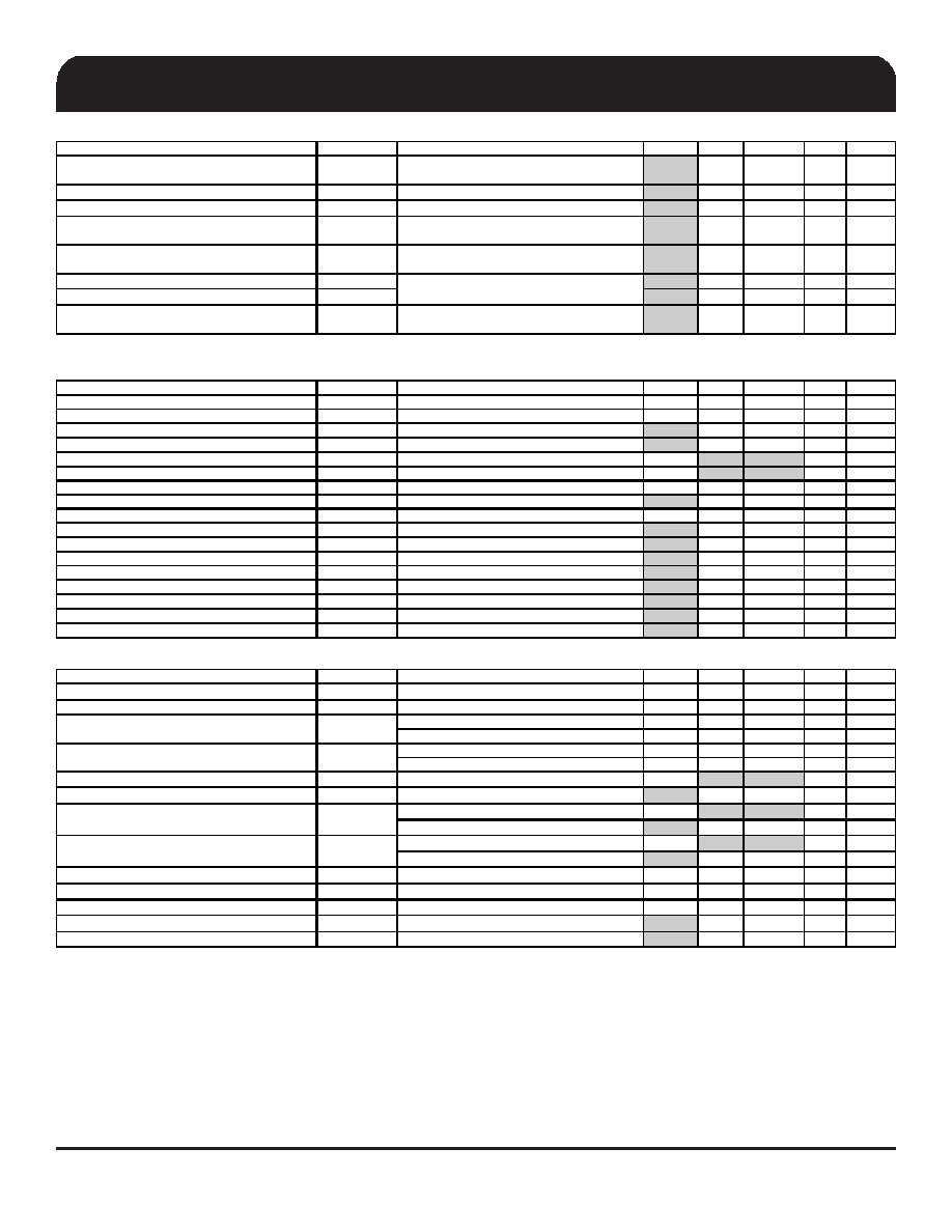
AC Electrical Characteristics - Input/Common Parameters
PARAMETER
SYMBOL
CONDITIONS
MIN
TYP
MAX
UNITS
Notes
Clk Stabilization
T
ST AB
From VDD Power-Up or de-assertion of PD to
1st clock
1.1
1.8
ms
Tdrive_PEREQ_off
T
D RPER OF F
Output stop after PEREQ# deasserted
2
3
clocks
Tdrive_PEREQ_on
TDRPERON
Output run after PEREQ# asserted
2
3
clocks
Tdrive_CPU
T
DRSR C
CPU output enable after
CPU_STOP# de-assertion
810
ns
Tdrive_PCIEX
T
DRPC IEX
PCIEX output enable after
PCI&PCIEX_STOP# de-assertion
815
ns
1
Tfall_SE
T
FALL
10
ns
Trise_SE
TRISE
10
ns
Tdrive_PD#
TDRPD
Differential output enable after
PD# de-assertion
85
300
us
1
Fall/rise time of all 3.3V control inputs from 20-
80%
AC Electrical Characteristics - CPU, PCIEX, SATA, DOT96MHz
PARAMETER
SYMBOL
CONDITIONS
MIN
TYP
MAX
UNITS NOTES
Rising Edge Slew Rate
tSLR
Differential Measurement
2.5
3.3
4
V/ns
1,2
Falling Edge Slew Rate
tFLR
Differential Measurement
2.5
3.2
4
V/ns
1,2
Slew Rate Variation
tSLVAR
Single-ended Measurement
16
20
%
1
Maximum Output Voltage
VHIGH
Includes overshoot
806
1150
mV
1
Minimum Output Voltage
VLOW
Includes undershoot
-300
mV
1
Differential Voltage Swing
VSWING
Differential Measurement
300
mV
1
Crossing Point VoltageVXABS
Single-ended Measurement
300
395
550
mV
1,3,4
Crossing Point Variation
VXABSVAR
Single-ended Measurement
32
140
mV
1,3,5
Duty Cycle
DCYC
Differential Measurement
45
49.7
55
%
1
CPU Jitter - Cycle to Cycle
CPUJC2C
Differential Measurement
66
85
ps1
CPU2_IPT Jitter - Cycle to Cycle
CPU2JC2C
Differential Measurement
125
150
ps1
SRC Jitter - Cycle to Cycle
SRCJC2C
Differential Measurement
66
125
ps1
SATA Jitter - Cycle to C ycle
SATAJC2C
Differential Measurement
66
125
ps1
DOT Jitter - Cycle to Cycle
DOTJC2C
Differential Measurement
65
250
ps1
CPU[1:0] Skew
CPUSKEW10
Differential Measurement
38
100
ps1,6
CPU[2_ITP:0] Skew
CPUSKEW20
Differential Measurement
145
150
ps1,6
SRC Skew
SRCSKEW
Differential Measurement
44
250
ps1
Electrical Characteristics - PCICLK/PCICLK_F
PARAMETER
SYMBOL
CON DITIONS
MIN
TYP
MAX
UNITS NOTES
Output Impedance
RDSP
VO = VDD*(0.5)
12
55
1
Long Accuracy
ppm
see Tperiod min-max values
-100
100
ppm
2
33.33MHz output no spread
29.99700
30.00300
ns
2
33.33MHz output spread
30.08421
30.23459
ns
2
33.33MHz output no spread
29.49700
30.50300
ns
2
33.33MHz output nominal/spread
29.56617
30.58421
ns
2
Output High Voltage
V
OH
I
OH = -1 mA
2.4
V
1
Output Low Voltage
VOL
IOL = 1 mA
0.4
V
1
V
OH @MIN = 1.0 V
-33
mA
1
V
OH @MA X = 3.1 35 V
-33
mA
1
VOL @ MIN = 1.95 V
30
mA
1
V
OL @ MA X = 0.4 V
38
mA
1
Rising Edge Slew Rate
tSLR
Measured from 0.8 to 2.0 V
1
1.7
4
V/ns
1
Falling Edge Slew Rate
t
FLR
Measured from 2.0 to 0.8 V
1
1.8
4
V/ns
1
Duty Cycle
d
t1
V
T = 1. 5 V
45
50.6
55
%1
Pin to Pin Skew
tskew
VT = 1.5 V
250
ps
1
Jitter, Cycle to cycle
t
jcyc-cyc
V
T = 1. 5 V
150
500
ps
1
*TA = Tambient; VDD = 3.3 V +/-5%; CL=5pF, Rs=22 (unless specified otherwise)
1 Guaranteed by design and characterization, not 100% tested in production.
2 All Long Term Accuracy and Clock Period specifications are guaranteed assuming that REFOUT is at 14.31818MHz
3 Slew rate emastured through V_swing voltage range centered about differential zero
4 Vcross is defined at the voltage where Clock = Clock#.
5 Only applies to the differential rising edge (Clock rising, Clock# falling.)
IOH
Output High Current
Tabs
Tperiod
Output Low Current
IOL
Clock period
Absolute min/max period
6 CPU group skew is nominally 0ps.
相關(guān)PDF資料 |
PDF描述 |
|---|---|
| 9LPRS436CKILFT | SPECIALTY MICROPROCESSOR CIRCUIT, PQCC48 |
| 9LPRS436CKILF | SPECIALTY MICROPROCESSOR CIRCUIT, PQCC48 |
| 9LPRS436CGLFT | SPECIALTY MICROPROCESSOR CIRCUIT, PDSO48 |
| 9LPRS436CGILF | SPECIALTY MICROPROCESSOR CIRCUIT, PDSO48 |
| 9LPRS462AGLFT | 240 MHz, OTHER CLOCK GENERATOR, PDSO8 |
相關(guān)代理商/技術(shù)參數(shù) |
參數(shù)描述 |
|---|---|
| 9LPRS437AFLF | 制造商:Integrated Device Technology Inc 功能描述:IDT 9LPRS437AFLF GENERAL PURPOSE SEMICONDUCTORS - Rail/Tube 制造商:Integrated Device Technology Inc 功能描述:IDT 9LPRS437AFLF General Purpose Semiconductors |
| 9LPRS437AFLFT | 制造商:Integrated Device Technology Inc 功能描述:IDT 9LPRS437AFLFT SEMICONDUCTORS - Tape and Reel 制造商:Integrated Device Technology Inc 功能描述:IDT 9LPRS437AFLFT Semiconductors |
| 9LPRS462AGLF | 功能描述:時(shí)鐘合成器/抖動(dòng)清除器 RoHS:否 制造商:Skyworks Solutions, Inc. 輸出端數(shù)量: 輸出電平: 最大輸出頻率: 輸入電平: 最大輸入頻率:6.1 GHz 電源電壓-最大:3.3 V 電源電壓-最小:2.7 V 封裝 / 箱體:TSSOP-28 封裝:Reel |
| 9LPRS462AGLFT | 功能描述:時(shí)鐘合成器/抖動(dòng)清除器 RoHS:否 制造商:Skyworks Solutions, Inc. 輸出端數(shù)量: 輸出電平: 最大輸出頻率: 輸入電平: 最大輸入頻率:6.1 GHz 電源電壓-最大:3.3 V 電源電壓-最小:2.7 V 封裝 / 箱體:TSSOP-28 封裝:Reel |
| 9LPRS464AGLF | 功能描述:時(shí)鐘合成器/抖動(dòng)清除器 RoHS:否 制造商:Skyworks Solutions, Inc. 輸出端數(shù)量: 輸出電平: 最大輸出頻率: 輸入電平: 最大輸入頻率:6.1 GHz 電源電壓-最大:3.3 V 電源電壓-最小:2.7 V 封裝 / 箱體:TSSOP-28 封裝:Reel |
發(fā)布緊急采購(gòu),3分鐘左右您將得到回復(fù)。