- 您現(xiàn)在的位置:買(mǎi)賣(mài)IC網(wǎng) > PDF目錄118869 > 7213J15CPE3 (ITT CANNON) ROCKER SWITCH, DPDT, LATCHED AND MOMENTARY, 0.02A, 20VDC, THROUGH HOLE-STRAIGHT PDF資料下載
參數(shù)資料
| 型號(hào): | 7213J15CPE3 |
| 廠商: | ITT CANNON |
| 元件分類(lèi): | 開(kāi)關(guān) |
| 英文描述: | ROCKER SWITCH, DPDT, LATCHED AND MOMENTARY, 0.02A, 20VDC, THROUGH HOLE-STRAIGHT |
| 封裝: | ROHS COMPLIANT |
| 文件頁(yè)數(shù): | 14/22頁(yè) |
| 文件大?。?/td> | 1631K |
| 代理商: | 7213J15CPE3 |
第1頁(yè)第2頁(yè)第3頁(yè)第4頁(yè)第5頁(yè)第6頁(yè)第7頁(yè)第8頁(yè)第9頁(yè)第10頁(yè)第11頁(yè)第12頁(yè)第13頁(yè)當(dāng)前第14頁(yè)第15頁(yè)第16頁(yè)第17頁(yè)第18頁(yè)第19頁(yè)第20頁(yè)第21頁(yè)第22頁(yè)
7000 Series
Miniature Rocker & Lever Handle Switches
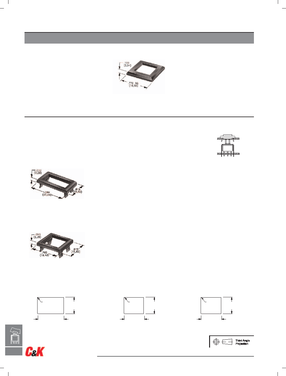
AVAILABLE HARDWARE
.495 – .505
(12,57 – 12,83)
.797 – .803
(20,24 – 20,40)
.005 R. MAX.
(0,13) TYP.
.495 – .505
(12,57 – 12,83)
.595 – .605
(15,11 – 15,37)
.005 R.
(0,13)
MAX. TYP.
.495 – .505
(12,57 – 12,83)
.620 – .625
(15,75 – 15,88)
.005 R.
(0,13)
MAX. TYP.
PANEL MOUNTING
For part numbers
4529xxxxx, 4527xxxxx,
4528xxxxx, 4526xxxxx
For part numbers
4325xxxxx, 4326xxxxx
For part numbers
4327xxxxx, 4328xxxxx
TYPICAL APPLICATION
NOTE: Other colors available, consult Customer Service Center.
Frame for J50, J60 & J90 Actuators
J1 & J2 Actuators
J50, J60 & J90 Actuators
MATTE
PART NO.
486701000 WHITE
486702000 BLACK
486703000
RED
Material: Nylon
GLOSS
PART NO.
486801000 WHITE
486802000 BLACK
486803000
RED
.125” (3,18) PANEL THK.
PART NO.
452601000 WHITE
452602263 BLACK
452603000
RED
.047” (1,19) PANEL THK.
PART NO.
452901000
452902263
452903000
.062” (1,57) PANEL THK.
PART NO.
452701000
452702263
452703000
.090” (2,29) PANEL THK.
PART NO.
452801000
452802263
452803000
.125” (3,18) PANEL THK.
PART NO.
432801000 WHITE
432802263 BLACK
432803000
RED
.047” (1,19) PANEL THK.
PART NO.
432501000
432502263
432503000
.062” (1,57) PANEL THK.
PART NO.
432601000
432602263
432603000
.090” (2,29) PANEL THK.
PART NO.
432701000
432702263
432703000
Frames snap into panel opening and are independent from switch mounting. Accurate positioning of the
PC mounted switch relative to the panel opening is necessary to provide proper clearance between actuator
and frame. Available in two basic styles and four panel thicknesses .047-.125 in. Material: Nylon. Finish: Matte.
H–24
H
Rocker
Dimensions are shown: Inch (mm)
Specifications and dimensions subject to change
www.ck-components.com
相關(guān)PDF資料 |
PDF描述 |
|---|---|
| 700C-SP7-B70-M6-R-E | PUSHBUTTON SWITCH, SPDT, LATCHED, 0.02A, 20VDC, THROUGH HOLE-RIGHT ANGLE |
| 700C-SP7-B71-VS3-R-E | PUSHBUTTON SWITCH, SPDT, LATCHED, 0.02A, 20VDC, THROUGH HOLE-STRAIGHT |
| 7301L41YW5GE2 | TOGGLE SWITCH, 3PDT, LATCHED, 5A, 28VDC, PANEL MOUNT |
| 700-DP7-M1-Q-E-AP2-RED-WHT | PUSHBUTTON SWITCH, DPDT, MOMENTARY, 3A, 28VDC, PANEL MOUNT |
| 700-DP7-M3-R-E-AP1-WHT-WHT | PUSHBUTTON SWITCH, DPDT, MOMENTARY, PANEL MOUNT |
相關(guān)代理商/技術(shù)參數(shù) |
參數(shù)描述 |
|---|---|
| 7213J15CQE2 | 功能描述:搖臂開(kāi)關(guān)與扳鈕開(kāi)關(guān) RoHS:否 制造商:C&K Components 觸點(diǎn)形式: 開(kāi)關(guān)功能: 電流額定值:50 mA 電壓額定值 AC: 電壓額定值 DC:30 V 功率額定值: 端接類(lèi)型: 執(zhí)行器:Paddle 顏色: 安裝風(fēng)格:Panel 端子密封: 觸點(diǎn)電鍍: 照明:Not Illuminated 照明顏色: |
| 7213J15ZQE2 | 功能描述:搖臂開(kāi)關(guān)與扳鈕開(kāi)關(guān) RoHS:否 制造商:C&K Components 觸點(diǎn)形式: 開(kāi)關(guān)功能: 電流額定值:50 mA 電壓額定值 AC: 電壓額定值 DC:30 V 功率額定值: 端接類(lèi)型: 執(zhí)行器:Paddle 顏色: 安裝風(fēng)格:Panel 端子密封: 觸點(diǎn)電鍍: 照明:Not Illuminated 照明顏色: |
| 7213J16CBE22 | 功能描述:搖臂開(kāi)關(guān)與扳鈕開(kāi)關(guān) RoHS:否 制造商:C&K Components 觸點(diǎn)形式: 開(kāi)關(guān)功能: 電流額定值:50 mA 電壓額定值 AC: 電壓額定值 DC:30 V 功率額定值: 端接類(lèi)型: 執(zhí)行器:Paddle 顏色: 安裝風(fēng)格:Panel 端子密封: 觸點(diǎn)電鍍: 照明:Not Illuminated 照明顏色: |
| 7213J16CKE32 | 功能描述:搖臂開(kāi)關(guān)與扳鈕開(kāi)關(guān) Rocker RoHS:否 制造商:C&K Components 觸點(diǎn)形式: 開(kāi)關(guān)功能: 電流額定值:50 mA 電壓額定值 AC: 電壓額定值 DC:30 V 功率額定值: 端接類(lèi)型: 執(zhí)行器:Paddle 顏色: 安裝風(fēng)格:Panel 端子密封: 觸點(diǎn)電鍍: 照明:Not Illuminated 照明顏色: |
| 7213J16CQE22 | 功能描述:搖臂開(kāi)關(guān)與扳鈕開(kāi)關(guān) RoHS:否 制造商:C&K Components 觸點(diǎn)形式: 開(kāi)關(guān)功能: 電流額定值:50 mA 電壓額定值 AC: 電壓額定值 DC:30 V 功率額定值: 端接類(lèi)型: 執(zhí)行器:Paddle 顏色: 安裝風(fēng)格:Panel 端子密封: 觸點(diǎn)電鍍: 照明:Not Illuminated 照明顏色: |
發(fā)布緊急采購(gòu),3分鐘左右您將得到回復(fù)。