- 您現(xiàn)在的位置:買賣IC網(wǎng) > PDF目錄24812 > 935263971112 (NXP SEMICONDUCTORS) SPECIALTY TELECOM CIRCUIT, PDSO28 PDF資料下載
參數(shù)資料
| 型號(hào): | 935263971112 |
| 廠商: | NXP SEMICONDUCTORS |
| 元件分類: | 通信及網(wǎng)絡(luò) |
| 英文描述: | SPECIALTY TELECOM CIRCUIT, PDSO28 |
| 封裝: | PLASTIC, SOT-136, SO-28 |
| 文件頁(yè)數(shù): | 7/38頁(yè) |
| 文件大小: | 287K |
| 代理商: | 935263971112 |
第1頁(yè)第2頁(yè)第3頁(yè)第4頁(yè)第5頁(yè)第6頁(yè)當(dāng)前第7頁(yè)第8頁(yè)第9頁(yè)第10頁(yè)第11頁(yè)第12頁(yè)第13頁(yè)第14頁(yè)第15頁(yè)第16頁(yè)第17頁(yè)第18頁(yè)第19頁(yè)第20頁(yè)第21頁(yè)第22頁(yè)第23頁(yè)第24頁(yè)第25頁(yè)第26頁(yè)第27頁(yè)第28頁(yè)第29頁(yè)第30頁(yè)第31頁(yè)第32頁(yè)第33頁(yè)第34頁(yè)第35頁(yè)第36頁(yè)第37頁(yè)第38頁(yè)

1999 Feb 17
15
Philips Semiconductors
Product specication
Cordless telephone, answering machine
line interface
UBA1707
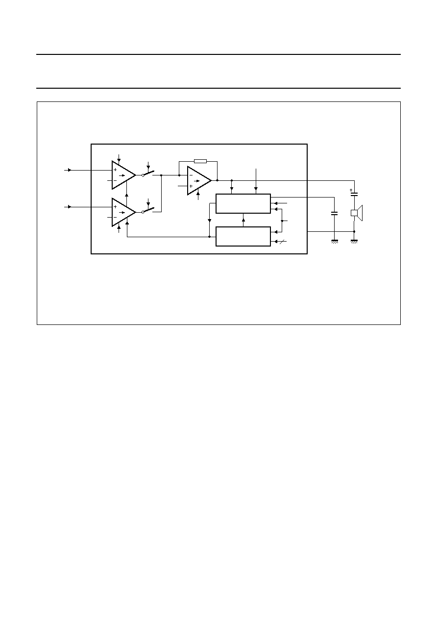
Fig.13 Loudspeaker channel.
Bit names are given in italics.
handbook, full pagewidth
MGK713
LSAI1
LSAI2
2Vd
LSPD
LSA2
LSA1
0.5VCC
DYNAMIC LIMITER
VOLUME CONTROL
VCC
UBA1707
DLCI
LSPD
VOL0
TO
VOL2
DLC
LSPGND
LSAO
3
VI
IV
LSP
CDLC
CLSAO
DYNAMIC LIMITER (PIN DLC; BIT DLCI)
The dynamic limiter of the UBA1707 prevents clipping of
the loudspeaker output stage and protects the operation of
the circuit when the supply voltage at VCC falls below
2.7 V.
Hard clipping of the loudspeaker output stage is prevented
by rapidly reducing the gain when the output stage starts
to saturate. The time in which gain reduction is effected
(clipping attack time) is approximately a few milliseconds.
The circuit stays in the reduced gain mode until the peaks
of the loudspeaker signals no longer cause saturation.
The gain of the loudspeaker amplifier then returns to its
normal value within the clipping release time (typically
250 ms). Both attack and release times are proportional to
the value of the capacitor CDLC. The total harmonic
distortion of the loudspeaker output stage, in reduced gain
mode, stays below 5% up to 10 dB (minimum) of input
voltage overdrive [providing VLSAI is below
500 mV (RMS)].
When the supply voltage drops below an internal threshold
voltage of 2.7 V, the gain of the loudspeaker amplifier is
rapidly reduced (approximately 1 ms). When the supply
voltage exceeds 2.7 V, the gain of the loudspeaker
amplifier is increased again.
The hard clipping of the dynamic limiter can be inhibited by
setting the DLCI bit at logic 1, via the serial interface.
The dynamic limiter is no longer supplied by setting the
LSPD bit at logic 1. In this case, the CDLC capacitor charge
is maintained to allow the gain of the loudspeaker amplifier
to return to its nominal value as soon as the loudspeaker
channel is supplied again.
VOLUME CONTROL (BITS VOL0, VOL1 AND VOL2)
The loudspeaker amplifier voltage gain can be reduced in
steps of 3 dB via the serial interface (via bits VOL0, VOL1
and VOL2). These bits provide 7 steps of voltage gain
adjustment. The voltage gain is maximum when all bits are
at logic 1 and is reduced by 21 dB when all bits are at
logic 0.
相關(guān)PDF資料 |
PDF描述 |
|---|---|
| 935263971118 | SPECIALTY TELECOM CIRCUIT, PDSO28 |
| 08-040831 | OUTLINE AUTO - TANGING MEGAPAC |
| 08-040831-C | OUTLINE AUTO - TANGING MEGAPAC |
| 08-040921 | OUTLINE MINI MEGAPAC STANDARD CHASSIS |
| 08-040921-D | OUTLINE MINI MEGAPAC STANDARD CHASSIS |
相關(guān)代理商/技術(shù)參數(shù) |
參數(shù)描述 |
|---|---|
| 935264217557 | 制造商:NXP Semiconductors 功能描述:SUB ONLY IC |
| 935267356112 | 制造商:NXP Semiconductors 功能描述:IC TEA1507PN |
| 935268081112 | 制造商:NXP Semiconductors 功能描述:SUB ONLY IC |
| 935268721125 | 制造商:NXP Semiconductors 功能描述:Buffer/Line Driver 1-CH Non-Inverting 3-ST CMOS 5-Pin TSSOP T/R |
| 935269304128 | 制造商:ST-Ericsson 功能描述:IC AUDIO CODEC W/TCH SCRN 48LQFP |
發(fā)布緊急采購(gòu),3分鐘左右您將得到回復(fù)。