- 您現(xiàn)在的位置:買賣IC網(wǎng) > PDF目錄24812 > 935263912557 (NXP SEMICONDUCTORS) 1 CHANNEL(S), 400M bps, SERIAL COMM CONTROLLER, PQFP100 PDF資料下載
參數(shù)資料
| 型號(hào): | 935263912557 |
| 廠商: | NXP SEMICONDUCTORS |
| 元件分類: | 微控制器/微處理器 |
| 英文描述: | 1 CHANNEL(S), 400M bps, SERIAL COMM CONTROLLER, PQFP100 |
| 封裝: | 14 X 14 MM, 1 MM HEIGHT, PLASTIC, SOT-386-1, TQFP-100 |
| 文件頁(yè)數(shù): | 36/56頁(yè) |
| 文件大小: | 277K |
| 代理商: | 935263912557 |
第1頁(yè)第2頁(yè)第3頁(yè)第4頁(yè)第5頁(yè)第6頁(yè)第7頁(yè)第8頁(yè)第9頁(yè)第10頁(yè)第11頁(yè)第12頁(yè)第13頁(yè)第14頁(yè)第15頁(yè)第16頁(yè)第17頁(yè)第18頁(yè)第19頁(yè)第20頁(yè)第21頁(yè)第22頁(yè)第23頁(yè)第24頁(yè)第25頁(yè)第26頁(yè)第27頁(yè)第28頁(yè)第29頁(yè)第30頁(yè)第31頁(yè)第32頁(yè)第33頁(yè)第34頁(yè)第35頁(yè)當(dāng)前第36頁(yè)第37頁(yè)第38頁(yè)第39頁(yè)第40頁(yè)第41頁(yè)第42頁(yè)第43頁(yè)第44頁(yè)第45頁(yè)第46頁(yè)第47頁(yè)第48頁(yè)第49頁(yè)第50頁(yè)第51頁(yè)第52頁(yè)第53頁(yè)第54頁(yè)第55頁(yè)第56頁(yè)

Philips Semiconductors
Preliminary specification
PDI1394L21
1394 full duplex AV link layer controller
2000 Jun 06
41
13.3
Asynchronous Control and Status Interface
13.3.1
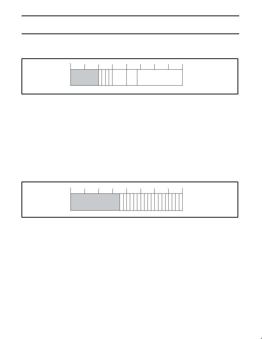
Asynchronous RX/TX Control (ASYCTL) – Base Address: 0x080
29 28 27 26 25 24 23 22 21 20 19 18 17 16 15 14 13 12 11 10 9 8 7 6 5 4 3 2 1 0
ARXALL
A
TXRST
ARXRST
SV00889
MAXRC
TOS
TOF
31 30
DIS_BCAST
Reset Value 0x00300320
Bit 23:
R/W
DIS_BCAST: Disable the reception of broadcast packets.
Bit 22:
R/W
ARXRST: Asynchronous receiver reset. This bit will auto clear when the link layer state machine is idle.
Bit 21:
R/W
ATXRST: Asynchronous transmitter reset
Bit 20:
R/W
ARXALL: Receive and filter only RESPONSE packets. When set (1), all responses are stored. When clear (0), only
solicited responses are stored.
Bit 19..16:
R/W
MAXRC: Maximum number of asynchronous transmitter single phase retries
Bit 15..13:
R/W
TOS: Time out seconds, integer of 1 second of the split transaction time out timer. Resets to “000”. This timer is set
to the maximum amount of time the transmitter will wait for a pending response before the transmitter will begin
transmitting the next available request packet. Also see TOF bits of this timer.
Bit 12..0:
R/W
TOF: Time out fractions, integer of 1/8000 second. Resets to 0320h, which is 100 milliseconds. During the timeout of
the split transaction timer, subsequent split transactions are blocked. If it is desired to transmit multiple split
transactions this can be accomplished by following this procedure: (1) set the split transaction timer value to “0”, (2)
disable the split time–out interrupt (TIMEOUT, bit 7 in register 0x0A0); (3) clear (set to “0”) the unsolicited response
filter bit (ARXALL, bit 20 in register 0x080). Now use tLabels (transaction Labels, see section 12.5.1) to pair
transmitted packets with received packets. Use software timers to time–out the subsequent pending responses.
13.3.2
Asynchronous RX/TX Memory Status (ASYMEM) – Base Address: 0x084
TREQQIDLE
RRSPQF
TREQQAF
TREQQ5A
V
29 28 27 26 25 24 23 22 21 20 19 18 17 16 15 14 13 12 11 10 9 8 7 6 5 4 3 2 1 0
TRSPQF
TRSPQAF
RREQQE
RREQQF
RREQQAF
RREQQ5A
V
RRSPQAF
RRSPQE
TRSPQ5A
V
RRSPQ5A
V
TREQQF
TRSPQE
TREQQE
31 30
SV00918
TRSPQIDLE
Reset Value 0x00033333
Unused bits read ‘0’. The information in this register is primarily used for diagnostics.
Bit 17:
R
TRSPQIDLE: Transmitter response queue is idle. Indicates that the transfer register for this queue is empty.
Bit 16:
R
TREQQIDLE: Transmitter request queue is idle. Indicates that the transfer register for this queue is empty.
Bit 15:
R
RRSPQF: Receiver response queue full.
Bit 14:
R
RRSPQAF: Receiver response queue almost full (precisely 1 more quadlet available).
Bit 13:
R
RRSPQ5AV: Receiver response queue at least 5 quadlets available.
Bit 12:
R
RRSPQE: Receiver response queue empty.
Bit 11:
R
RREQQF: Receiver request queue full.
Bit 10:
R
RREQQAF: Receiver request queue almost full (precisely 1 more quadlet available).
Bit 9:
R
RREQQ5AV: Receiver request queue at least 5 quadlets available.
Bit 8:
R
RREQQE: Receiver request queue empty.
Bit 7:
R
TRSPQF: Transmitter response queue full.
Bit 6:
R
TRSPQAF: Transmitter response queue almost full (precisely 1 more quadlet available).
Bit 5:
R
TRSPQ5AV: Transmitter response queue at least 5 quadlets available.
Bit 4:
R
TRSPQE: Transmitter response queue empty.
Bit 3:
R
TREQQF: Transmitter request queue full.
Bit 2:
R
TREQQAF: Transmitter request queue almost full (precisely 1 more quadlet available).
Bit 1:
R
TREQQ5AV: Transmitter request queue at least 5 quadlets available.
Bit 0:
R
TREQQE: Transmitter request queue empty.
相關(guān)PDF資料 |
PDF描述 |
|---|---|
| 935263912551 | 1 CHANNEL(S), 400M bps, SERIAL COMM CONTROLLER, PQFP100 |
| 08-1101-00 | DREHSCHALTER 1POL 12STELLUNGEN |
| 08-1260-00 | ************GESTRICHEN************ |
| 08-1341-00 | DREHSCHALTER 3POL 4STELLUNGEN |
| 08-2101-00 | DREHSCHALTER 2POL 12STELLUNGEN |
相關(guān)代理商/技術(shù)參數(shù) |
參數(shù)描述 |
|---|---|
| 935264217557 | 制造商:NXP Semiconductors 功能描述:SUB ONLY IC |
| 935267356112 | 制造商:NXP Semiconductors 功能描述:IC TEA1507PN |
| 935268081112 | 制造商:NXP Semiconductors 功能描述:SUB ONLY IC |
| 935268721125 | 制造商:NXP Semiconductors 功能描述:Buffer/Line Driver 1-CH Non-Inverting 3-ST CMOS 5-Pin TSSOP T/R |
| 935269304128 | 制造商:ST-Ericsson 功能描述:IC AUDIO CODEC W/TCH SCRN 48LQFP |
發(fā)布緊急采購(gòu),3分鐘左右您將得到回復(fù)。