- 您現(xiàn)在的位置:買賣IC網(wǎng) > PDF目錄382822 > 74LS138 (Fairchild Semiconductor Corporation) Decoder/Demultiplexer PDF資料下載
參數(shù)資料
| 型號(hào): | 74LS138 |
| 廠商: | Fairchild Semiconductor Corporation |
| 英文描述: | Decoder/Demultiplexer |
| 中文描述: | 解碼器/解復(fù)用器 |
| 文件頁(yè)數(shù): | 3/7頁(yè) |
| 文件大小: | 81K |
| 代理商: | 74LS138 |
3
www.fairchildsemi.com
D
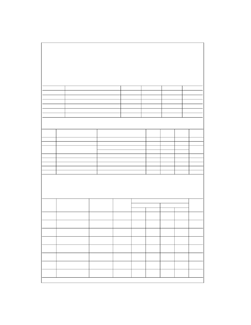
Absolute Maximum Ratings
(Note 2)
Note 2:
The “Absolute Maximum Ratings” are those values beyond which
the safety of the device cannot be guaranteed. The device should not be
operated at these limits. The parametric values defined in the Electrical
Characteristics tables are not guaranteed at the absolute maximum ratings.
The “Recommended Operating Conditions” table will define the conditions
for actual device operation.
DM74LS138 Recommended Operating Conditions
DM74LS138 Electrical Characteristics
over recommended operating free air temperature range (unless otherwise noted)
Note 3:
All typicals are at V
CC
=
5V, T
A
=
25
°
C.
Note 4:
Not more than one output should be shorted at a time, and the duration should not exceed one second.
Note 5:
I
CC
is measured with all outputs enabled and OPEN.
DM74LS138 Switching Characteristics
at V
CC
=
5V and T
A
=
25
°
C
Supply Voltage
Input Voltage
Operating Free Air Temperature Range
Storage Temperature Range
7V
7V
0
°
C to
+
70
°
C
65
°
C to
+
150
°
C
Symbol
Parameter
Min
4.75
2
Nom
5
Max
5.25
Units
V
V
V
mA
mA
°
C
V
CC
V
IH
V
IL
I
OH
I
OL
T
A
Supply Voltage
HIGH Level Input Voltage
LOW Level Input Voltage
HIGH Level Output Current
LOW Level Output Current
Free Air Operating Temperature
0.8
0.4
8
70
0
Symbol
Parameter
Conditions
Min
Typ
Max
Units
(Note 3)
V
I
V
OH
V
OL
Input Clamp Voltage
V
CC
=
Min, I
I
=
18 mA
V
CC
=
Min, I
OH
=
Max, V
IL
=
Max, V
IH
=
Min
V
CC
=
Min, I
OL
=
Max, V
IL
=
Max, V
IH
=
Min
I
OL
=
4 mA, V
CC
=
Min
V
CC
=
Max, V
I
=
7V
V
CC
=
Max, V
I
=
2.7V
V
CC
=
Max, V
I
=
0.4V
V
CC
=
Max (Note 4)
V
CC
=
Max (Note 5)
1.5
V
HIGH Level Output Voltage
LOW Level
Output Voltage
2.7
3.4
0.35
0.25
V
0.5
0.4
V
I
I
I
IH
I
IL
I
OS
I
CC
Input Current @ Max Input Voltage
HIGH Level Input Current
LOW Level Input Current
0.1
20
0.36
100
10
mA
μ
A
mA
Short Circuit Output Current
Supply Current
20
mA
mA
6.3
From (Input)
Levels
R
L
=
2 k
Symbol
Parameter
To (Output)
of Delay
C
L
=
15 pF
Min
C
L
=
50 pF
Min
Units
Max
Max
t
PLH
Propagation Delay Time
LOW-to-HIGH Level Output
Select to Output
2
18
27
ns
t
PHL
Propagation Delay Time
HIGH-to-LOW Level Output
Propagation Delay Time
Select to Output
2
27
40
ns
t
PLH
Select to Output
3
18
27
ns
LOW-to-HIGH Level Output
Propagation Delay Time
HIGH-to-LOW Level Output
t
PHL
Select to Output
3
27
40
ns
t
PLH
Propagation Delay Time
LOW-to-HIGH Level Output
Propagation Delay Time
Enable to Output
2
18
27
ns
t
PHL
Enable to Output
2
24
40
ns
HIGH-to-LOW Level Output
Propagation Delay Time
LOW-to-HIGH Level Output
t
PLH
Enable to Output
3
18
27
ns
t
PHL
Propagation Delay Time
HIGH-to-LOW Level Output
Enable to Output
3
28
40
ns
相關(guān)PDF資料 |
PDF描述 |
|---|---|
| 74LS165 | 8-Bit Parallel In/Serial Output Shift Registers |
| 74LS253 | 3-STATE Data Selector/Multiplexer |
| 74LS573 | Octal D-Type Latch with 3-STATE Outputs |
| 74LS574 | Octal D-Type Flip-Flop with 3-STATE Outputs |
| 74LVCZ161284A | LOW VOLTAGE HIGH SPEED IEEE 1284 TRANSCEIVER WITH ERROR-FREE POWER-UP |
相關(guān)代理商/技術(shù)參數(shù) |
參數(shù)描述 |
|---|---|
| 74LS138 WAF | 制造商:Texas Instruments 功能描述: |
| 74LS138DC | 制造商:Rochester Electronics LLC 功能描述:- Bulk |
| 74LS138N | 制造商:Misc 功能描述: |
| 74LS138PC | 制造商:Rochester Electronics LLC 功能描述:- Bulk |
| 74LS138P-E | 制造商:Renesas Electronics 功能描述:Cut Tape 制造商:Renesas 功能描述:Decoder/Demultiplexer Single 3-to-8 16-Pin PDIP Tube |
發(fā)布緊急采購(gòu),3分鐘左右您將得到回復(fù)。