- 您現(xiàn)在的位置:買(mǎi)賣IC網(wǎng) > PDF目錄68811 > 71M6541G-IGTR/F (MAXIM INTEGRATED PRODUCTS INC) SPECIALTY ANALOG CIRCUIT, PQFP64 PDF資料下載
參數(shù)資料
| 型號(hào): | 71M6541G-IGTR/F |
| 廠商: | MAXIM INTEGRATED PRODUCTS INC |
| 元件分類: | 模擬信號(hào)調(diào)理 |
| 英文描述: | SPECIALTY ANALOG CIRCUIT, PQFP64 |
| 封裝: | LEAD FREE, LQFP-64 |
| 文件頁(yè)數(shù): | 135/165頁(yè) |
| 文件大小: | 2208K |
| 代理商: | 71M6541G-IGTR/F |
第1頁(yè)第2頁(yè)第3頁(yè)第4頁(yè)第5頁(yè)第6頁(yè)第7頁(yè)第8頁(yè)第9頁(yè)第10頁(yè)第11頁(yè)第12頁(yè)第13頁(yè)第14頁(yè)第15頁(yè)第16頁(yè)第17頁(yè)第18頁(yè)第19頁(yè)第20頁(yè)第21頁(yè)第22頁(yè)第23頁(yè)第24頁(yè)第25頁(yè)第26頁(yè)第27頁(yè)第28頁(yè)第29頁(yè)第30頁(yè)第31頁(yè)第32頁(yè)第33頁(yè)第34頁(yè)第35頁(yè)第36頁(yè)第37頁(yè)第38頁(yè)第39頁(yè)第40頁(yè)第41頁(yè)第42頁(yè)第43頁(yè)第44頁(yè)第45頁(yè)第46頁(yè)第47頁(yè)第48頁(yè)第49頁(yè)第50頁(yè)第51頁(yè)第52頁(yè)第53頁(yè)第54頁(yè)第55頁(yè)第56頁(yè)第57頁(yè)第58頁(yè)第59頁(yè)第60頁(yè)第61頁(yè)第62頁(yè)第63頁(yè)第64頁(yè)第65頁(yè)第66頁(yè)第67頁(yè)第68頁(yè)第69頁(yè)第70頁(yè)第71頁(yè)第72頁(yè)第73頁(yè)第74頁(yè)第75頁(yè)第76頁(yè)第77頁(yè)第78頁(yè)第79頁(yè)第80頁(yè)第81頁(yè)第82頁(yè)第83頁(yè)第84頁(yè)第85頁(yè)第86頁(yè)第87頁(yè)第88頁(yè)第89頁(yè)第90頁(yè)第91頁(yè)第92頁(yè)第93頁(yè)第94頁(yè)第95頁(yè)第96頁(yè)第97頁(yè)第98頁(yè)第99頁(yè)第100頁(yè)第101頁(yè)第102頁(yè)第103頁(yè)第104頁(yè)第105頁(yè)第106頁(yè)第107頁(yè)第108頁(yè)第109頁(yè)第110頁(yè)第111頁(yè)第112頁(yè)第113頁(yè)第114頁(yè)第115頁(yè)第116頁(yè)第117頁(yè)第118頁(yè)第119頁(yè)第120頁(yè)第121頁(yè)第122頁(yè)第123頁(yè)第124頁(yè)第125頁(yè)第126頁(yè)第127頁(yè)第128頁(yè)第129頁(yè)第130頁(yè)第131頁(yè)第132頁(yè)第133頁(yè)第134頁(yè)當(dāng)前第135頁(yè)第136頁(yè)第137頁(yè)第138頁(yè)第139頁(yè)第140頁(yè)第141頁(yè)第142頁(yè)第143頁(yè)第144頁(yè)第145頁(yè)第146頁(yè)第147頁(yè)第148頁(yè)第149頁(yè)第150頁(yè)第151頁(yè)第152頁(yè)第153頁(yè)第154頁(yè)第155頁(yè)第156頁(yè)第157頁(yè)第158頁(yè)第159頁(yè)第160頁(yè)第161頁(yè)第162頁(yè)第163頁(yè)第164頁(yè)第165頁(yè)
v1.1
2008–2011 Teridian Semiconductor Corporation
71
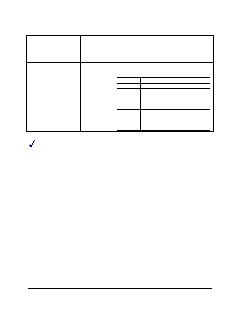
Table 60: EECTRL Bits for 2-pin Interface
Status
Bit
Name
Read/
Write
Reset
State
Polarity
Description
7
ERROR
R
0
Positive
1 when an illegal command is received.
6
BUSY
R
0
Positive
1 when serial data bus is busy.
5
RX_ACK
R
1
Positive
1 indicates that the EEPROM sent an ACK bit.
4
TX_ACK
R
1
Positive
1 indicates that an ACK bit has been sent to the
EEPROM.
3:0
CMD[3:0]
W
0000
Positive
CMD[3:0]
Operation
0000
No-op command.
0010
Receive a byte from the EEPROM
and send ACK.
0011
Transmit a byte to the EEPROM.
0101
Issue a STOP sequence.
0110
Receive the last byte from the
EEPROM and do not send ACK.
1001
Issue a START sequence.
Others
No operation, set the ERROR bit.
The EEPROM interface can also be operated by controlling the DIO2 and DIO3 pins directly. The
direction of the DIO line can be changed from input to output and an output value can be written
with a single write operation, thus avoiding collisions (see Table 15 Port Registers (SEGDIO0-15)).
Therefore, no resistor is required in series SDATA to protect against collisions.
2.5.9.2 Three-wire (-Wire) EEPROM Interface with Single Data Pin
A 500 kHz three-wire interface, using SDATA, SDCK, and a DIO pin for CS is available. The interface is
selected by setting DIO_EEX[1:0] = 10. The EECTRL bits when the three-wire interface is selected are
shown in Table 61. When EECTRL is written, up to 8 bits from EEDATA are either written to the EEPROM
or read from the EEPROM, depending on the values of the EECTRL bits.
2.5.9.3 Three-wire (-Wire/SPI) EEPROM Interface with Separate Di/DO Pins
If DIO_EEX[1:0]=11, the three-wire interface is the same as above, except DI and DO are separate pins.
In this case, SEGDIO3 becomes DO and SEGDIO8 becomes DI. The timing diagrams are the same as
for DIO_EEX[1:0]=10 except that all output data appears on DO and all input data is expected on DI. In
this mode, DI is ignored while data is being received on DO. This mode is compatible with SPI modes 0,0
and 1,1 where data is shifted out on the falling edge of the clock and is strobed in on the rising edge of
the clock.
Table 61: EECTRL Bits for the 3-wire Interface
Control
Bit
Name
Read/
Write
Description
7
WFR
W
Wait for Ready. If this bit is set, the trailing edge of BUSY is delayed until
a rising edge is seen on the data line. This bit can be used during the
last byte of a Write command to cause the INT5 interrupt to occur when
the EEPROM has finished its internal write sequence. This bit is ignored
if Hi-Z=0.
6
BUSY
R
Asserted while the serial data bus is busy. When the BUSY bit falls, an
INT5 interrupt occurs.
5
HiZ
W
Indicates that the SD signal is to be floated to high impedance immediately
after the last SDCK rising edge.
相關(guān)PDF資料 |
PDF描述 |
|---|---|
| 71M6541F-IGTR/F | SPECIALTY ANALOG CIRCUIT, PQFP64 |
| 71M6541D-IGTR/F | SPECIALTY ANALOG CIRCUIT, PQFP64 |
| 71M6542F-IGTR/F | SPECIALTY ANALOG CIRCUIT, PQFP100 |
| 71M6541D-IGT/F | SPECIALTY ANALOG CIRCUIT, PQFP64 |
| 71M6542G-IGT/F | SPECIALTY ANALOG CIRCUIT, PQFP100 |
相關(guān)代理商/技術(shù)參數(shù) |
參數(shù)描述 |
|---|---|
| 71M6541GT-IGT/F | 功能描述:IC ENERGY METER 64-LQFP 制造商:maxim integrated 系列:Single Converter Technology? 包裝:托盤(pán) 零件狀態(tài):停產(chǎn) 輸入阻抗:- 測(cè)量誤差:0.1% 電壓 - I/O 高:2V 電壓 - I/O 低:0.8V 電流 - 電源:- 電壓 - 電源:3 V ~ 3.6 V 表計(jì)類型:單相 工作溫度:-40°C ~ 85°C 安裝類型:表面貼裝 封裝/外殼:64-LQFP 供應(yīng)商器件封裝:64-LQFP(10x10) 標(biāo)準(zhǔn)包裝:1,000 |
| 71M6541GT-IGTR/F | 功能描述:IC ENERGY METER 64-LQFP 制造商:maxim integrated 系列:Single Converter Technology? 包裝:帶卷(TR) 零件狀態(tài):停產(chǎn) 輸入阻抗:- 測(cè)量誤差:0.1% 電壓 - I/O 高:2V 電壓 - I/O 低:0.8V 電流 - 電源:- 電壓 - 電源:3 V ~ 3.6 V 表計(jì)類型:單相 工作溫度:-40°C ~ 85°C 安裝類型:表面貼裝 封裝/外殼:64-LQFP 供應(yīng)商器件封裝:64-LQFP(10x10) 標(biāo)準(zhǔn)包裝:1,500 |
| 71M6542F | 制造商:未知廠家 制造商全稱:未知廠家 功能描述:71M6541D/71M6541F/71M6541G/71M6542F/71M6542G 是 TeridianTM 的第4 代高集成度單相電表SoC |
| 71M6542F-IGT/F | 功能描述:計(jì)量片上系統(tǒng) - SoC Precision Energy Meter IC RoHS:否 制造商:Maxim Integrated 核心:80515 MPU 處理器系列:71M6511 類型:Metering SoC 最大時(shí)鐘頻率:70 Hz 程序存儲(chǔ)器大小:64 KB 數(shù)據(jù) RAM 大小:7 KB 接口類型:UART 可編程輸入/輸出端數(shù)量:12 片上 ADC: 安裝風(fēng)格:SMD/SMT 封裝 / 箱體:LQFP-64 封裝:Reel |
| 71M6542F-IGTR/F | 功能描述:計(jì)量片上系統(tǒng) - SoC Precision Energy Meter IC RoHS:否 制造商:Maxim Integrated 核心:80515 MPU 處理器系列:71M6511 類型:Metering SoC 最大時(shí)鐘頻率:70 Hz 程序存儲(chǔ)器大小:64 KB 數(shù)據(jù) RAM 大小:7 KB 接口類型:UART 可編程輸入/輸出端數(shù)量:12 片上 ADC: 安裝風(fēng)格:SMD/SMT 封裝 / 箱體:LQFP-64 封裝:Reel |
發(fā)布緊急采購(gòu),3分鐘左右您將得到回復(fù)。