- 您現(xiàn)在的位置:買賣IC網(wǎng) > PDF目錄68811 > 71M6541D-IGTR/F (MAXIM INTEGRATED PRODUCTS INC) SPECIALTY ANALOG CIRCUIT, PQFP64 PDF資料下載
參數(shù)資料
| 型號: | 71M6541D-IGTR/F |
| 廠商: | MAXIM INTEGRATED PRODUCTS INC |
| 元件分類: | 模擬信號調(diào)理 |
| 英文描述: | SPECIALTY ANALOG CIRCUIT, PQFP64 |
| 封裝: | LEAD FREE, LQFP-64 |
| 文件頁數(shù): | 102/165頁 |
| 文件大小: | 2208K |
| 代理商: | 71M6541D-IGTR/F |
第1頁第2頁第3頁第4頁第5頁第6頁第7頁第8頁第9頁第10頁第11頁第12頁第13頁第14頁第15頁第16頁第17頁第18頁第19頁第20頁第21頁第22頁第23頁第24頁第25頁第26頁第27頁第28頁第29頁第30頁第31頁第32頁第33頁第34頁第35頁第36頁第37頁第38頁第39頁第40頁第41頁第42頁第43頁第44頁第45頁第46頁第47頁第48頁第49頁第50頁第51頁第52頁第53頁第54頁第55頁第56頁第57頁第58頁第59頁第60頁第61頁第62頁第63頁第64頁第65頁第66頁第67頁第68頁第69頁第70頁第71頁第72頁第73頁第74頁第75頁第76頁第77頁第78頁第79頁第80頁第81頁第82頁第83頁第84頁第85頁第86頁第87頁第88頁第89頁第90頁第91頁第92頁第93頁第94頁第95頁第96頁第97頁第98頁第99頁第100頁第101頁當(dāng)前第102頁第103頁第104頁第105頁第106頁第107頁第108頁第109頁第110頁第111頁第112頁第113頁第114頁第115頁第116頁第117頁第118頁第119頁第120頁第121頁第122頁第123頁第124頁第125頁第126頁第127頁第128頁第129頁第130頁第131頁第132頁第133頁第134頁第135頁第136頁第137頁第138頁第139頁第140頁第141頁第142頁第143頁第144頁第145頁第146頁第147頁第148頁第149頁第150頁第151頁第152頁第153頁第154頁第155頁第156頁第157頁第158頁第159頁第160頁第161頁第162頁第163頁第164頁第165頁
v1.1
2008–2011 Teridian Semiconductor Corporation
41
the corresponding interrupt flag can be individually enabled or disabled by the interrupt enable bits in the
IEN0 (SFR 0xA8), IEN1 (SFR 0xB8), and IEN2 (SFR 0x9A).
Figure 16 shows the device interrupt structure.
Referring to Figure 16, interrupt sources can originate from within the 80515 MPU core (referred to as
Internal Sources) or can originate from other parts of the 71M654x SoC (referred to as External Sources).
There are seven external interrupt sources, as seen in the leftmost part of Figure 16, and in Table 26 and
Table 27 (i.e., EX0-EX6).
Interrupt Overview
When an interrupt occurs, the MPU vectors to the predetermined address as shown in Table 38. Once
the interrupt service has begun, it can be interrupted only by a higher priority interrupt. The interrupt service
is terminated by a return from interrupt instruction, RETI. When a RETI instruction is performed, the
processor returns to the instruction that would have been next when the interrupt occurred.
When the interrupt condition occurs, the processor also indicates this by setting a flag bit. This bit is set
regardless of whether the interrupt is enabled or disabled. Each interrupt flag is sampled once per
machine cycle, and then samples are polled by the hardware. If the sample indicates a pending interrupt
when the interrupt is enabled, then the interrupt request flag is set. On the next instruction cycle, the
interrupt is acknowledged by hardware forcing an LCALL to the appropriate vector address, if the
following conditions are met:
No interrupt of equal or higher priority is already in progress.
An instruction is currently being executed and is not completed.
The instruction in progress is not RETI or any write access to the registers IEN0, IEN1, IEN2, IP0 or IP1.
Special Function Registers for Interrupts
The following SFR registers control the interrupt functions:
The interrupt enable registers: IEN0, IEN1 and IEN2 (see Table 26, Table 27 and Table 28).
The Timer/Counter control registers, TCON and T2CON (see
The interrupt request register, IRCON (see Table 31).
The interrupt priority registers: IP0 and IP1 (see Table 36).
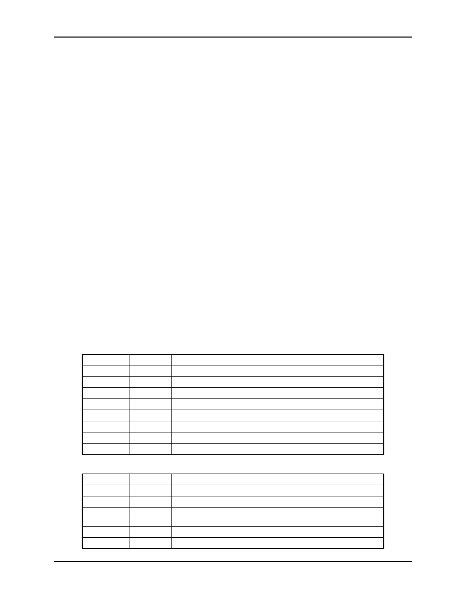
Table 26: The IEN0 Bit Functions (SFR 0xA8)
Bit
Symbol
Function
IEN0[7]
EAL
EAL = 0 disables all interrupts.
IEN0[6]
WDT
Not used for interrupt control.
IEN0[5]
–
Not Used.
IEN0[4]
ES0
ES0 = 0 disables serial channel 0 interrupt.
IEN0[3]
ET1
ET1 = 0 disables timer 1 overflow interrupt.
IEN0[2]
EX1
EX1 = 0 disables external interrupt 1: DIO status change
IEN0[1]
ET0
ET0 = 0 disables timer 0 overflow interrupt.
IEN0[0]
EX0
EX0 = 0 disables external interrupt 0: DIO status change
Table 27: The IEN1 Bit Functions (SFR 0xB8)
Bit
Symbol
Function
IEN1[7]
–
Not used.
IEN1[6]
–
Not used.
IEN1[5]
EX6
EX6 = 0 disables external interrupt 6:
XFER_BUSY, RTC_1S, RTC_1M or RTC_T
IEN1[4]
EX5
EX5 = 0 disables external interrupt 5: EEPROM or SPI
IEN1[3]
EX4
EX4 = 0 disables external interrupt 4: VSTAT
相關(guān)PDF資料 |
PDF描述 |
|---|---|
| 71M6542F-IGTR/F | SPECIALTY ANALOG CIRCUIT, PQFP100 |
| 71M6541D-IGT/F | SPECIALTY ANALOG CIRCUIT, PQFP64 |
| 71M6542G-IGT/F | SPECIALTY ANALOG CIRCUIT, PQFP100 |
| 71M6541G-IGT/F | SPECIALTY ANALOG CIRCUIT, PQFP64 |
| 71M6541F-IGT/F | SPECIALTY ANALOG CIRCUIT, PQFP64 |
相關(guān)代理商/技術(shù)參數(shù) |
參數(shù)描述 |
|---|---|
| 71M6541DT-IGT/F | 制造商:Maxim Integrated Products 功能描述:ENERGY METER ICS - Rail/Tube |
| 71M6541DT-IGTR/F | 制造商:Maxim Integrated Products 功能描述:1-PHASE SOC, 32KB FLASH, PRES TEMP SENSOR - Tape and Reel |
| 71M6541F | 制造商:未知廠家 制造商全稱:未知廠家 功能描述:71M6541D/71M6541F/71M6541G/71M6542F/71M6542G 是 TeridianTM 的第4 代高集成度單相電表SoC |
| 71M6541F-DB | 功能描述:開發(fā)板和工具包 - 8051 71M6541 Eval Kit RoHS:否 制造商:Silicon Labs 產(chǎn)品:Development Kits 工具用于評估:C8051F960, Si7005 核心: 接口類型:USB 工作電源電壓: |
| 71M6541F-IGT/F | 功能描述:計量片上系統(tǒng) - SoC Precision Energy Meter IC RoHS:否 制造商:Maxim Integrated 核心:80515 MPU 處理器系列:71M6511 類型:Metering SoC 最大時鐘頻率:70 Hz 程序存儲器大小:64 KB 數(shù)據(jù) RAM 大小:7 KB 接口類型:UART 可編程輸入/輸出端數(shù)量:12 片上 ADC: 安裝風(fēng)格:SMD/SMT 封裝 / 箱體:LQFP-64 封裝:Reel |
發(fā)布緊急采購,3分鐘左右您將得到回復(fù)。