- 您現(xiàn)在的位置:買(mǎi)賣(mài)IC網(wǎng) > PDF目錄157280 > 5962-9855202QXC 32-BIT, 16 MHz, RISC MICROCONTROLLER, CPGA144 PDF資料下載
參數(shù)資料
| 型號(hào): | 5962-9855202QXC |
| 元件分類(lèi): | 微控制器/微處理器 |
| 英文描述: | 32-BIT, 16 MHz, RISC MICROCONTROLLER, CPGA144 |
| 封裝: | CERAMIC, PGA-144 |
| 文件頁(yè)數(shù): | 28/64頁(yè) |
| 文件大小: | 1464K |
| 代理商: | 5962-9855202QXC |
第1頁(yè)第2頁(yè)第3頁(yè)第4頁(yè)第5頁(yè)第6頁(yè)第7頁(yè)第8頁(yè)第9頁(yè)第10頁(yè)第11頁(yè)第12頁(yè)第13頁(yè)第14頁(yè)第15頁(yè)第16頁(yè)第17頁(yè)第18頁(yè)第19頁(yè)第20頁(yè)第21頁(yè)第22頁(yè)第23頁(yè)第24頁(yè)第25頁(yè)第26頁(yè)第27頁(yè)當(dāng)前第28頁(yè)第29頁(yè)第30頁(yè)第31頁(yè)第32頁(yè)第33頁(yè)第34頁(yè)第35頁(yè)第36頁(yè)第37頁(yè)第38頁(yè)第39頁(yè)第40頁(yè)第41頁(yè)第42頁(yè)第43頁(yè)第44頁(yè)第45頁(yè)第46頁(yè)第47頁(yè)第48頁(yè)第49頁(yè)第50頁(yè)第51頁(yè)第52頁(yè)第53頁(yè)第54頁(yè)第55頁(yè)第56頁(yè)第57頁(yè)第58頁(yè)第59頁(yè)第60頁(yè)第61頁(yè)第62頁(yè)第63頁(yè)第64頁(yè)
34
7.1.3 Continue Command
The Continue Execution Command allows the user to resume
program execution from the point where the Monitor mode of
operation was entered. The Continue Execution command
takes the form:
C0-Resume execution with Timers A and B halted.
C1- Resume execution with Timer A on and Timer B off.
C2 - Resume execution with Timer A off and Timer B on.
C3- Resume execution with Timers A and B on.
7.1.4 Run Command
The Run From Memory Location Command allows the user to
start program execution from any point within the 1M port
space. This command takes the form Rxxxxn where “xxxxx”
denotes the 20-bit starting address. Valid characters for the
address field (xxxx) are 0-9 and A-F. The value n is either 0,1,2,
or 3 and is defined:
0 - Resume execution with Timers A and B halted.
1 - Resume execution with Timer A on and Timer B off.
2 - Resume execution with Timer A off and Timer B on.
3 - Resume execution with Timers A and B on.
8.0 UART Operation
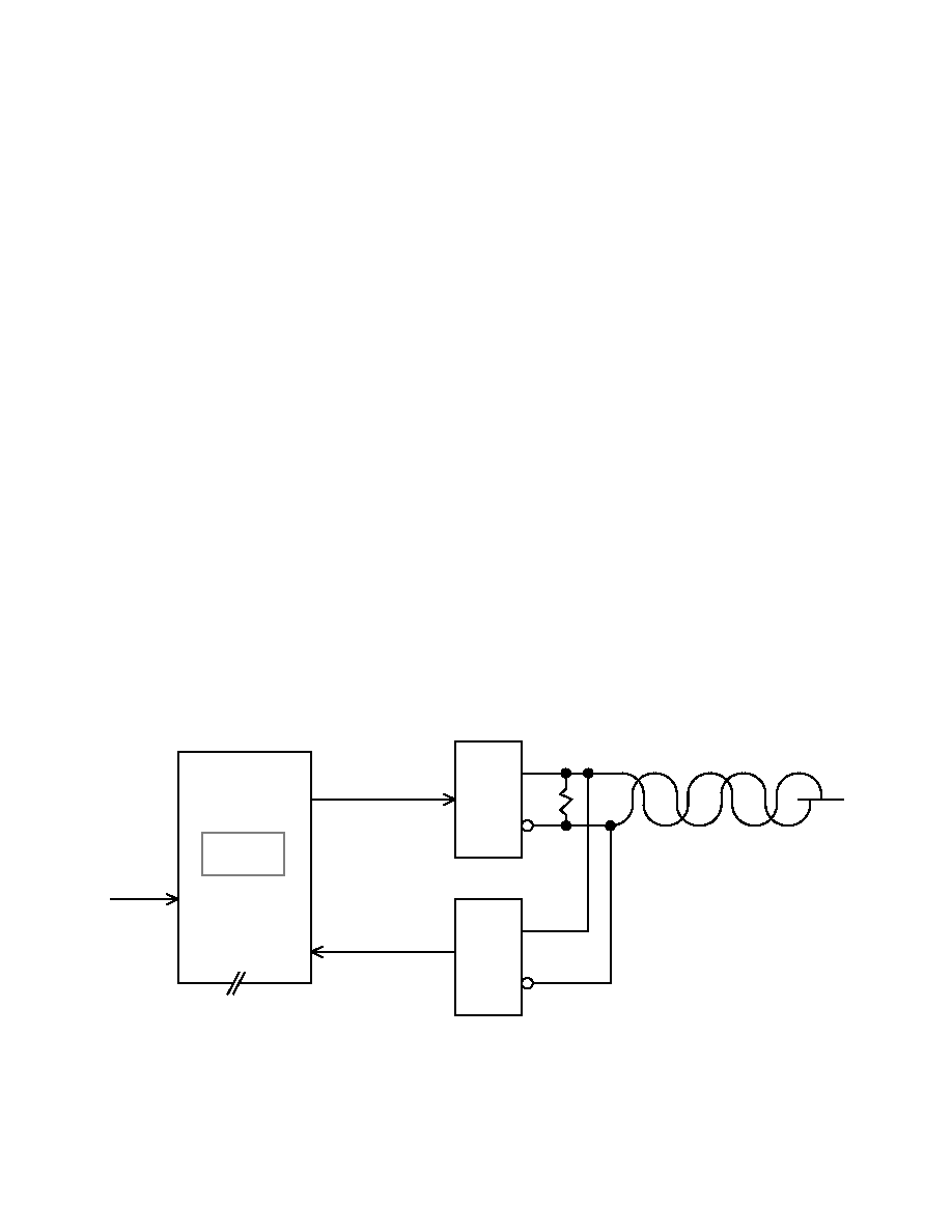
The UT69R000 has an internal UART. Figure 29 shows a
diagram of the UT69R000 connected to a serial bus. The UART
operates at a fixed frequency of 9600 baud with eight bits, one
stop bit, and odd parity. The idle state for the UART is logic
zero. The TIMCLK input fixes the baud rate of the UART
(9600 baud at TIMCLK equal to 12 MHz). TIMCLK also
controls the frequency of the internal timers (TA and TB). The
status of the UART is read from the System Status Register
(STATUS) bits 7 through 0.
8.1 UART Transmitter Operation
The transmitter portion of the UT69R000’s UART is a double-
buffered configuration consisting of a Transmitter Register and
a Transmitter Buffer Register. The Transmitter Register
contains the serial data stream the UT69R000 is currently
transmitting through the UART; the Transmitter Buffer
Register contains the next message to transmit through the
UART. The system programmer reads the status of the
Transmitter Register from bit 1 (TE) of the Status and the status
of the Transmitter Buffer Register from bit 2 (TBE) of the
Status Register. If bit 2 of the Status register is a logical one,
the UART transmitter buffer is ready for data, once loaded with
data, bit 2 transitions to a logical zero. Bit 1 is a logical zero
during serial transmission and transitions to a logical one when
transmission from the Transmitter Register is complete. The
Status register is read using Input Register Instruction INR
Rd,STATUS.
To initiate a serial data transmission, the system designer must
first load the data to transmit into the Transmitter Buffer
Register with the Output Register Instruction OTR Rd, TXMT.
This instruction loads the least significant byte of the source
register specified in the instruction into the Transmitter Buffer
Register. At this time, TBE goes low and the UT69R000
automatically transfers the data word into the Transmitter
Register. After the transfer is complete, TE goes low and TBE
transition to a logical one indicating a serial transmission is
about to begin and the next data word can be loaded into the
Transmitter Buffer Register.
Figure 29. Serial Data Bus Interface to the UT69R000
AND ODD PARITY
ONE STOP BIT
EIGHT DATA BITS,
9600 BAUD
SERIAL RS-232 BUS X0106-
RCVR
BUS
SERIAL
DRVR
BUS
SERIAL
UT69R000
FOR UART
12 MHz I/P
TIMCLK
UARTIN
UARTOUT
相關(guān)PDF資料 |
PDF描述 |
|---|---|
| 5962-9855202QXX | 32-BIT, 16 MHz, RISC MICROCONTROLLER, CPGA144 |
| 5962F9855202QXA | 32-BIT, 16 MHz, RISC MICROCONTROLLER, CPGA144 |
| 5962G9855201QXX | 32-BIT, 12 MHz, RISC MICROCONTROLLER, CPGA144 |
| 5962G9855202VXA | 32-BIT, 16 MHz, RISC MICROCONTROLLER, CPGA144 |
| 5962G9855202VXX | 32-BIT, 16 MHz, RISC MICROCONTROLLER, CPGA144 |
相關(guān)代理商/技術(shù)參數(shù) |
參數(shù)描述 |
|---|---|
| 5962-9855501VPA | 功能描述:計(jì)時(shí)器和支持產(chǎn)品 QML Class V Prec Timer RoHS:否 制造商:Micrel 類(lèi)型:Standard 封裝 / 箱體:SOT-23 內(nèi)部定時(shí)器數(shù)量:1 電源電壓-最大:18 V 電源電壓-最小:2.7 V 最大功率耗散: 最大工作溫度:+ 85 C 最小工作溫度:- 40 C 封裝:Reel |
| 59629856401QEA | 制造商:TI 功能描述:SNJ5447AJ |
| 5962-9856401QEA | 制造商:Texas Instruments 功能描述:Decoder/Driver Single 4-to-7 16-Pin CDIP Tube |
| 5962-9858401QFA | 功能描述:LVDS 接口集成電路 RoHS:否 制造商:Texas Instruments 激勵(lì)器數(shù)量:4 接收機(jī)數(shù)量:4 數(shù)據(jù)速率:155.5 Mbps 工作電源電壓:5 V 最大功率耗散:1025 mW 最大工作溫度:+ 85 C 封裝 / 箱體:SOIC-16 Narrow 封裝:Reel |
| 5962-9858501QFA | 功能描述:總線接收器 RoHS:否 制造商:Texas Instruments 接收機(jī)數(shù)量:4 接收機(jī)信號(hào)類(lèi)型:Differential 接口類(lèi)型:EIA/TIA-422-B, V.11 工作電源電壓:3.3 V 最大工作溫度:+ 85 C 最小工作溫度:- 40 C 封裝 / 箱體:TSSOP-16 封裝:Reel |
發(fā)布緊急采購(gòu),3分鐘左右您將得到回復(fù)。