- 您現(xiàn)在的位置:買賣IC網(wǎng) > PDF目錄30621 > 2SK3753-01R (FUJI ELECTRIC CO LTD) 13 A, 600 V, 0.65 ohm, N-CHANNEL, Si, POWER, MOSFET PDF資料下載
參數(shù)資料
| 型號(hào): | 2SK3753-01R |
| 廠商: | FUJI ELECTRIC CO LTD |
| 元件分類: | JFETs |
| 英文描述: | 13 A, 600 V, 0.65 ohm, N-CHANNEL, Si, POWER, MOSFET |
| 文件頁(yè)數(shù): | 1/4頁(yè) |
| 文件大?。?/td> | 126K |
| 代理商: | 2SK3753-01R |
1
Item
Symbol
Ratings
Unit
Remarks
Drain-source voltage
VDS
600
Continuous Drain Current
ID
±13
Pulsed Drain Current
ID(puls]
±52
Gate-Source Voltage
VGS
±30
Maximum Avalanche current
IAR
13
Non-Repetitive
EAS
216.7
Maximum Avalanche Energy
Maximum Drain-Source dV/dt
dVDS/dt
20
Peak Diode Recovery dV/dt
dV/dt
5
Max. Power Dissipation
PD
95
3.13
Operating and Storage
Tch
+150
Temperature range
Tstg
Isolation Voltage
VISO
2
Electrical characteristics (Tc =25°C unless otherwise specified)
Thermal characteristics
2SK3753-01R
FUJI POWER MOSFET
Maximum ratings and characteristic
Absolute maximum ratings
(Tc=25°C unless otherwise specified)
Item
Symbol
Test Conditions
Zero Gate Voltage Drain Current
IDSS
VDS=600V VGS=0V
VDS=480V VGS=0V
VGS=±30V
ID=6A
VGS=10V
ID=6A
VDS=25V
VCC=300V
ID=6A
VGS=10V
RGS=10
Min.
Typ.
Max.
Units
V
A
nA
S
pF
nC
A
V
s
C
ns
Min.
Typ.
Max.
Units
Thermal resistance
Rth(ch-c)
channel to case
Rth(ch-a)
channel to ambient
1.32
40.0
°C/W
Symbol
BVDSS
VGS(th)
IGSS
RDS(on)
gfs
Ciss
Coss
Crss
td(on)
tr
td(off)
tf
QG
QGS
QGD
IAV
VSD
trr
Qrr
Item
Drain-Source Breakdown Voltage
Gate Threshold Voltage
Gate-Source Leakage Current
Drain-Source On-State Resistance
Forward Transconductance
Input Capacitance
Output Capacitance
Reverse Transfer Capacitance
Turn-On Time ton
Turn-Off Time toff
Total Gate Charge
Gate-Source Charge
Gate-Drain Charge
Avalanche Capability
Diode forward on-voltage
Reverse recovery time
Reverse recovery charge
Test Conditions
ID= 250A
VGS=0V
ID= 250A
VDS=VGS
Tch=25°C
Tch=125°C
VDS=0V
VDS=25V
VGS=0V
f=1MH
VCC=300V
ID=12A
VGS=10V
L=2.36mH Tch=25°C
IF=12A VGS=0V Tch=25°C
IF=12A VGS=0V
-di/dt=100A/s
Tch=25°C
V
A
V
A
mJ
kV/s
W
°C
kVrms
600
3.0
5.0
25
250
10
100
0.50
0.65
5.5
11
1600
2400
160
240
7
10.5
18
27
16
24
35
50
815
34
51
12.5
19
11.5
17.5
13
1.00
1.50
0.75
6.5
-55 to +150
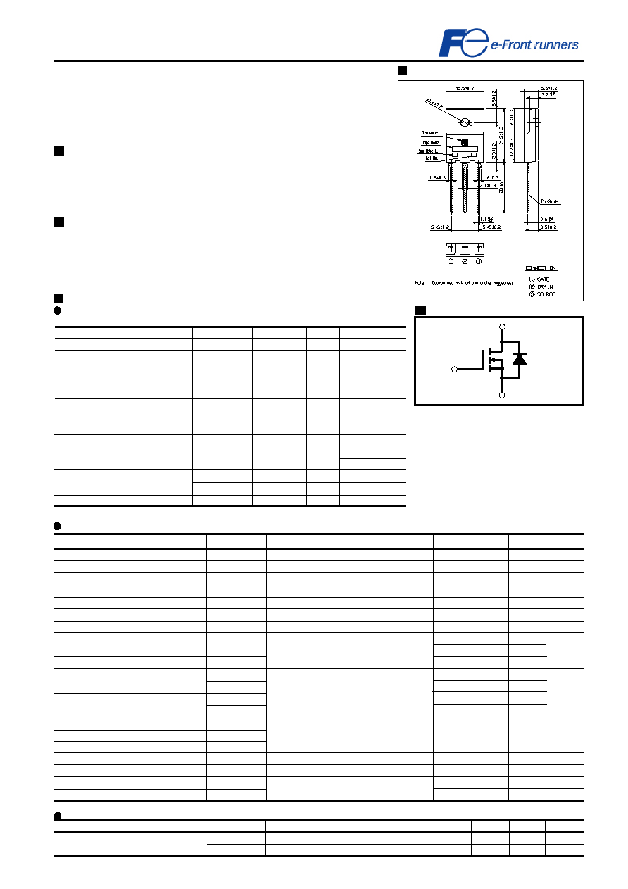
Outline Drawings (mm)
www.fujielectric.co.jp/fdt/scd
Super FAP-G Series
N-CHANNEL SILICON POWER MOSFET
Equivalent circuit schematic
200406
Note *1
Note *2
VDS 600V
Note *4
Tc=25°C
Ta=25°C
t=60sec. f=60Hz
=
<
Features
High speed switching
Low on-resistance
No secondary breakdown
Low driving power
Avalanche-proof
Applications
Switching regulators
DC-DC converters
UPS (Uninterruptible Power Supply)
Gate(G)
Source(S)
Drain(D)
Note *1:Tch
150°C,Repetitive and Non-repetitive
Note *2:StartingTch=25°C,IL=2.36mH,VCC=60V
EAS limited by maximum channel temperature
and Avalanche current.
See to the ‘Avalanche Energy’ graph
Note *3:Repetitive rating:Pulse width limited by
maximum channel temperature.
See to the ‘Transient Thermal impedance’
graph.
Note *4:IF -ID, -di/dt = 50A/
s,VCC BVDSS,Tch 150°C
=
<
=
<
=
<
=
<
相關(guān)PDF資料 |
PDF描述 |
|---|---|
| 2SK3756 | UHF BAND, Si, N-CHANNEL, RF SMALL SIGNAL, MOSFET |
| 2SK3770-01MR | 26 A, 120 V, 0.078 ohm, N-CHANNEL, Si, POWER, MOSFET, TO-220AB |
| 2SK3811-ZP | 110 A, 40 V, 0.0018 ohm, N-CHANNEL, Si, POWER, MOSFET, TO-263AB |
| 2SK3813-Z | 60 mA, 40 V, N-CHANNEL, Si, SMALL SIGNAL, MOSFET, TO-252AA |
| 2SK3813 | 60 mA, 40 V, N-CHANNEL, Si, SMALL SIGNAL, MOSFET, TO-251AA |
相關(guān)代理商/技術(shù)參數(shù) |
參數(shù)描述 |
|---|---|
| 2SK3753-01RSC | 制造商:Fuji Electric 功能描述: |
| 2SK3754(F) | 制造商:Toshiba America Electronic Components 功能描述: |
| 2SK3755-AZ | 制造商:Renesas Electronics Corporation 功能描述: 制造商:Renesas Electronics Corporation 功能描述:Trans MOSFET N-CH 40V 45A 3-Pin(3+Tab) TO-220 |
| 2SK3756(TE12L,F) | 制造商:Toshiba America Electronic Components 功能描述:MOSFER N-ch 7.5V 1A 470MHz PW-Mini |
| 2SK3757(Q) | 功能描述:MOSFET PW MOSFET N-Ch 450V 2A 2.45 Ohm RoHS:否 制造商:STMicroelectronics 晶體管極性:N-Channel 汲極/源極擊穿電壓:650 V 閘/源擊穿電壓:25 V 漏極連續(xù)電流:130 A 電阻汲極/源極 RDS(導(dǎo)通):0.014 Ohms 配置:Single 最大工作溫度: 安裝風(fēng)格:Through Hole 封裝 / 箱體:Max247 封裝:Tube |
發(fā)布緊急采購(gòu),3分鐘左右您將得到回復(fù)。