- 您現(xiàn)在的位置:買賣IC網(wǎng) > PDF目錄371386 > 240VA (Lattice Semiconductor Corporation) In-System Programmable 3.3V Generic Digital CrosspointTM PDF資料下載
參數(shù)資料
| 型號: | 240VA |
| 廠商: | Lattice Semiconductor Corporation |
| 英文描述: | In-System Programmable 3.3V Generic Digital CrosspointTM |
| 中文描述: | 在系統(tǒng)可編程3.3V的通用數(shù)字CrosspointTM |
| 文件頁數(shù): | 11/25頁 |
| 文件大小: | 324K |
| 代理商: | 240VA |

11
Specifications
ispGDX240VA
ADVANCED
27
28
29
30
31
32
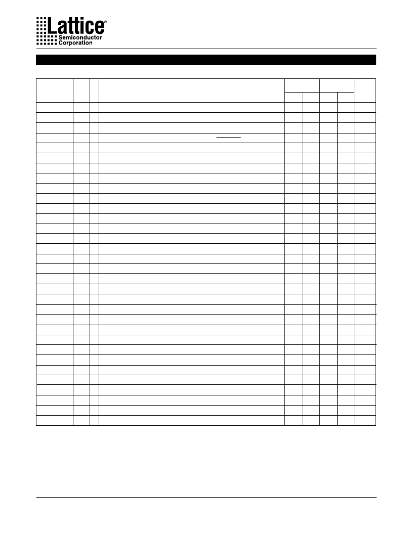
Output Skew (tgco1 Across Chip)
1. All timings measured with one output switching, fast output slew rate setting, except
t
sl
.
2. The delay parameters are measured with Vcc as I/O voltage reference. An additional 0.5ns delay is incurred when Vccio is
used as I/O voltage reference.
7.0
7.0
–
–
–
–
–
–
–
–
–
–
–
–
–
–
–
–
7.0
11.0
9.0
13.0
8.5
8.5
8.5
8.5
–
–
18.0
–
7.0
0.5
1
2
3
4
5
6
7
8
9
10
11
12
13
14
15
16
17
18
19
20
21
22
23
24
25
26
Data Prop. Delay from Any I/O pin to Any I/O Pin (4:1 MUX)
Data Prop. Delay from MUXsel Inputs to Any Output (4:1 MUX)
Clock Frequency, Max. Toggle
Clock Frequency with External Feedback
Input Latch or Register Setup Time Before Y
x
Input Latch or Register Setup Time Before I/O Clock
Output Latch or Register Setup Time Before Y
x
Output Latch or Register Setup Time Before I/O Clock
Global Clock Enable Setup Time Before Y
x
Global Clock Enable Setup Time Before I/O Clock
I/O Clock Enable Setup Time Before Y
x
Input Latch or Reg. Hold Time (Y
x
)
Input Latch or Reg. Hold Time (I/O Clock)
Output Latch or Reg. Hold Time (Y
x
)
Output Latch or Reg. Hold Time (I/O Clock)
Global Clock Enable Hold Time (Y
x
)
Global Clock Enable Hold Time (I/O Clock)
I/O Clock Enable Hold Time (Y
x
)
Output Latch or Reg. Clock (from Y
x
) to Output Delay
Input Latch or Register Clock (from Y
x
) to Output Delay
Output Latch or Register Clock (from I/O pin) to Output Delay
Input Latch or Register Clock (from I/O pin) to Output Delay
Input to Output Enable
Input to Output Disable
Test OE Output Enable
Test OE Output Disable
Clock Pulse Duration, High
Clock Pulse Duration, Low
Register Reset Delay from RESET Low
Reset Pulse Width
Output Delay Adder for Output Timings Using Slow Slew Rate
External Timing Parameters
Over Recommended Operating Conditions
ns
ns
MHz
MHz
ns
ns
ns
ns
ns
ns
ns
ns
ns
ns
ns
ns
ns
ns
ns
ns
ns
ns
ns
ns
ns
ns
ns
ns
ns
ns
ns
ns
–
–
100
80
5.5
4.5
5.5
4.5
3.5
2.5
6.5
0.0
2.5
0.0
2.5
0.0
2.5
0.0
–
–
–
–
–
–
–
–
5.0
5.0
–
14.0
–
–
A
A
–
–
–
–
–
–
–
–
–
–
–
–
–
–
–
–
A
A
A
A
B
C
B
C
–
–
–
–
D
A
t
pd
2
t
sel
2
f
max (Tog.)
f
max (Ext.)
t
su1
t
su2
t
su3
t
su4
t
suce1
t
suce2
t
suce3
t
h1
t
h2
t
h3
t
h4
t
hce1
t
hce2
t
hce3
t
gco1
2
t
gco2
2
t
co1
2
t
co2
2
t
en
2
t
dis
2
t
toeen
2
t
toedis
2
t
wh
t
wl
t
rst
t
rw
t
sl
t
sk
DESCRIPTION
PARAMETER
( )
1
UNITS
-7
MIN. MAX.
#
4.5
4.5
–
–
–
–
–
–
–
–
–
–
–
–
–
–
–
–
4.5
8.5
6.0
9.5
6.0
6.0
7.0
7.0
–
–
14.0
–
4.5
0.5
–
–
200
111
4.0
3.0
4.0
3.0
2.5
1.5
4.5
0.0
1.5
0.0
1.5
0.0
1.5
0.0
–
–
–
–
–
–
–
–
3.5
3.5
–
10.0
–
–
-4
MIN. MAX.
TEST
1
COND.
相關(guān)PDF資料 |
PDF描述 |
|---|---|
| 241101 | USB PANEL SOCKET PCB TYPE B |
| 241102 | USB PANEL SOCKET PCB TYPE B |
| 2412F | MESSUHR BEREICH 0.4ZOLL STOSSFEST LEICHT |
| 2413.2433 | LED MODULE RECTANGULAR RED |
| 2413.2434 | LED MODULE RECTANGULAR RED |
相關(guān)代理商/技術(shù)參數(shù) |
參數(shù)描述 |
|---|---|
| 240x | 制造商:LIGHTING COMP DESIGN 功能描述: 制造商:Lighting Components & Design Inc 功能描述: |
| 240X10019X | 制造商:Conec Corporation 功能描述: |
| 240X10049X | 功能描述:D-Sub工具與硬件 37 POS FERRITE BLOCK RoHS:否 制造商:3M Electronic Solutions Division 產(chǎn)品:Accessories 類型:Strain Relief, 36 Position 用于:Wiremount D-Sub Connectors |
| 240X180X150 | 制造商:ELSTEEL 功能描述:WALL BOX L240XH180XW150MM |
| 240Y | 功能描述:存儲箱與外殼 4-7/8 x 8-7/8 x 3-7/8 Yellow RoHS:否 制造商:Tektronix 顏色:Black 材料:Polypropylene 尺寸:23.25 in L x 20.75 in W x 9 in H |
發(fā)布緊急采購,3分鐘左右您將得到回復(fù)。