- 您現(xiàn)在的位置:買賣IC網(wǎng) > PDF目錄371367 > 20V8 (Cypress Semiconductor Corp.) Flash Erasable, Reprogrammable CMOS PAL Device PDF資料下載
參數(shù)資料
| 型號(hào): | 20V8 |
| 廠商: | Cypress Semiconductor Corp. |
| 元件分類: | PAL |
| 英文描述: | Flash Erasable, Reprogrammable CMOS PAL Device |
| 中文描述: | 閃光可擦除,可再編程的CMOS PAL制式設(shè)備 |
| 文件頁數(shù): | 4/14頁 |
| 文件大?。?/td> | 352K |
| 代理商: | 20V8 |

PALCE20V8
Document #: 38-03026 Rev. **
Page 4 of 14
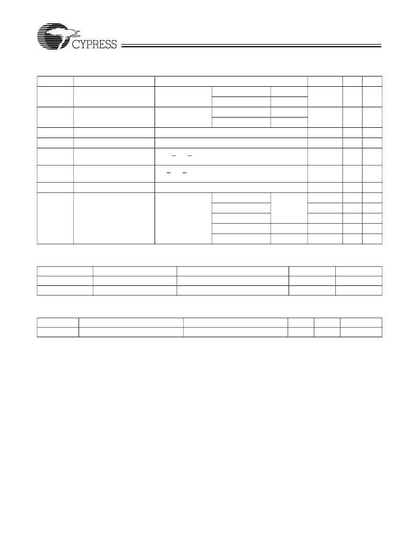
Electrical Characteristics
Over the Operating Range
[2]
Parameter
V
OH
Description
Test Conditions
I
OH
=
3.2 mA
I
OH
=
2 mA
I
OL
= 24 mA
I
OL
= 12 mA
Min.
2.4
Max.
Unit
V
Output HIGH Voltage
V
CC
= Min.,
V
IN
= V
IH
or V
IL
Com
’
l
Mil/Ind
Com
’
l
Mil/Ind
V
OL
Output LOW Voltage
V
CC
= Min.,
V
IN
= V
IH
or V
IL
0.5
V
V
IH
V
IL[4]
I
IH
Input HIGH Level
Input LOW Level
Input or I/O HIGH Leakage
Current
Input or I/O LOW Leakage
Current
Output Short Circuit Current V
CC
= Max., V
OUT
= 0.5V
[6,7]
Operating Power Supply
Current
Guaranteed Input Logical HIGH Voltage for All Inputs
[3]
Guaranteed Input Logical LOW Voltage for All Inputs
[3]
3.5V < V
IN
< V
CC
2.0
0.5
V
V
μ
A
0.8
10
I
IL[5]
0V < V
IN
< V
IN
(Max.)
100
μ
A
I
SC
I
CC
30
150
115
90
55
130
65
mA
mA
mA
mA
mA
mA
V
CC
= Max.,
V
IL
= 0V, V
IH
= 3V,
Output Open,
f = 15 MHz
(counter)
5, 7, 10 ns
15, 25 ns
15L, 25L ns
10, 15, 25 ns
15L, 25L ns
Com
’
l
Mil/Ind
Mil/Ind
Capacitance
[7]
Parameter
Description
Test Conditions
V
IN
= 2.0V @ f = 1 MHz
V
OUT
= 2.0V @ f = 1 MHz
Typ.
5
5
Unit
pF
pF
C
IN
C
OUT
Input Capacitance
Output Capacitance
Endurance Characteristics
[7]
Parameter
N
Description
Test Conditions
Normal Programming Conditions
Min.
100
Max.
Unit
Cycles
Minimum Reprogramming Cycles
Notes:
2.
3.
4.
5.
6.
See the last page of this specification for Group A subgroup testing information.
These are absolute values with respect to device ground. All overshoots due to system or tester noise are included.
V
(Min.) is equal to
3.0V for pulse durations less than 20 ns.
The leakage current is due to the internal pull-up resistor on all pins.
Not more than one output should be tested at a time. Duration of the short circuit should not be more than one second. V
OUT
= 0.5V has been chosen to avoid test problems
caused by tester ground degradation.
Tested initially and after any design or process changes that may affect these parameters.
7.
相關(guān)PDF資料 |
PDF描述 |
|---|---|
| 20 | ALUSOL 22SWG 500G |
| 21-0117G | PACKAGE OUTLINE, 2x2 UCSP |
| 21-0159 | 21-0159 |
| 210007039-002 | 350mWAudio Power Amplifier with Shutdown Mode |
| 21001 | SICHERHEITSSCHALTER CADET 1N/C 1N/O |
相關(guān)代理商/技術(shù)參數(shù) |
參數(shù)描述 |
|---|---|
| 20V8-25QP | 制造商: 功能描述: 制造商:undefined 功能描述: |
| 20VAL12HW3C | 制造商:HB 制造商全稱:HB Electronic Components 功能描述:LED |
| 20VB | 制造商:未知廠家 制造商全稱:未知廠家 功能描述:General Purpose RFI Power Line Filters General Purpose for High Impedance Loads at Low Cost |
| 20VB1 | 功能描述:電源線濾波器 20A 1/4" FASTON FLANGE MOUNT RoHS:否 制造商:EPCOS 電壓額定值:277 VAC 電流額定值:100 A 安裝風(fēng)格:Chassis 端接類型:Screw |
| 20VB10A | 制造商:Energizer Battery Company 功能描述:9V Clip Holder - Snap Connector |
發(fā)布緊急采購,3分鐘左右您將得到回復(fù)。