- 您現(xiàn)在的位置:買賣IC網(wǎng) > PDF目錄11830 > XR17C158CV-F (Exar Corporation)IC UART PCI BUS 5V OCTAL 144LQFP PDF資料下載
參數(shù)資料
| 型號: | XR17C158CV-F |
| 廠商: | Exar Corporation |
| 文件頁數(shù): | 56/67頁 |
| 文件大?。?/td> | 0K |
| 描述: | IC UART PCI BUS 5V OCTAL 144LQFP |
| 產(chǎn)品培訓(xùn)模塊: | UART Product Overview |
| 標(biāo)準(zhǔn)包裝: | 60 |
| 特點(diǎn): | * |
| 通道數(shù): | 8 |
| FIFO's: | 64 字節(jié) |
| 規(guī)程: | RS485 |
| 電源電壓: | 4.5 V ~ 5.5 V |
| 帶自動流量控制功能: | 是 |
| 帶IrDA 編碼器/解碼器: | 是 |
| 帶故障啟動位檢測功能: | 是 |
| 帶調(diào)制解調(diào)器控制功能: | 是 |
| 安裝類型: | 表面貼裝 |
| 封裝/外殼: | 144-LQFP |
| 供應(yīng)商設(shè)備封裝: | 144-LQFP(20x20) |
| 包裝: | 托盤 |
| 其它名稱: | 1016-1287 |
第1頁第2頁第3頁第4頁第5頁第6頁第7頁第8頁第9頁第10頁第11頁第12頁第13頁第14頁第15頁第16頁第17頁第18頁第19頁第20頁第21頁第22頁第23頁第24頁第25頁第26頁第27頁第28頁第29頁第30頁第31頁第32頁第33頁第34頁第35頁第36頁第37頁第38頁第39頁第40頁第41頁第42頁第43頁第44頁第45頁第46頁第47頁第48頁第49頁第50頁第51頁第52頁第53頁第54頁第55頁當(dāng)前第56頁第57頁第58頁第59頁第60頁第61頁第62頁第63頁第64頁第65頁第66頁第67頁
XR17C158
xr
5V PCI BUS OCTAL UART
REV. 1.4.3
6
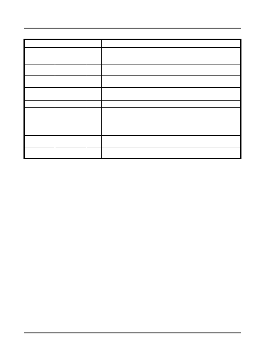
NOTE: Pin type: I=Input, O=Output, IO= Input/output, OD=Output Open Drain.
EECS
115
O
Chip select to a EEPROM device like 93C46. It is manually selectable thru the
Configuration Register REGB. Requires a pull-up 4.7K ohm resistor for exter-
nal sensing of EEPROM during power up. See DAN112 for further details.
EEDI
114
O
Write data to EEPROM device. It is manually accessible thru the Configura-
tion Register REGB.
EEDO
113
I
Read data from EEPROM device. It is manually accessible thru the Configu-
ration Register REGB.
XTAL1
110
I
Crystal or external clock input.
XTAL2
109
O
Crystal or buffered clock output.
TMRCK
69
I
16-bit timer/counter external clock input.
ENIR
70
I
Infrared mode enable (active high). This pin is sampled during power up, fol-
lowing a hardware reset (RST#) or soft-reset (register RESET). It can be used
to start up all 8 UARTs in the infrared mode. The sampled logic state is trans-
ferred to MCR bit-6 in the UART.
TEST#
111
I
Factory Test. Connect to VCC for normal operation.
VCC
4,19,34,45,64,
90,112,137
+5V power supply. For a pin-to-pin compatible device that operates at 3.3V,
see the XR17D158.
GND
5,20,35,46,63,
89,136
Power supply common, ground.
Pin Description
NAME
PIN #TYPE
DESCRIPTION
相關(guān)PDF資料 |
PDF描述 |
|---|---|
| XR17D158CV-F | IC UART PCI BUS OCTAL 144LQFP |
| ATMEGA168-15MZ | MCU AVR 16K FLASH 15MHZ 32-QFN |
| XR17V258IVTR-F | IC UART PCI BUS OCTAL 144LQFP |
| XR16L788IQTR-F | IC UART FIFO 64B OCTAL 100QFP |
| XR17C154IV-F | IC UART PCI BUS QUAD 144LQFP |
相關(guān)代理商/技術(shù)參數(shù) |
參數(shù)描述 |
|---|---|
| XR17C158CVTR-F | 制造商:Exar Corporation 功能描述:UART 8-CH 64Byte FIFO 5V 144-Pin LQFP T/R 制造商:Exar Corporation 功能描述:XR17C158CVTR-F |
| XR17C158IV | 功能描述:UART 接口集成電路 UART RoHS:否 制造商:Texas Instruments 通道數(shù)量:2 數(shù)據(jù)速率:3 Mbps 電源電壓-最大:3.6 V 電源電壓-最小:2.7 V 電源電流:20 mA 最大工作溫度:+ 85 C 最小工作溫度:- 40 C 封裝 / 箱體:LQFP-48 封裝:Reel |
| XR17C158IV-F | 功能描述:UART 接口集成電路 UART RoHS:否 制造商:Texas Instruments 通道數(shù)量:2 數(shù)據(jù)速率:3 Mbps 電源電壓-最大:3.6 V 電源電壓-最小:2.7 V 電源電流:20 mA 最大工作溫度:+ 85 C 最小工作溫度:- 40 C 封裝 / 箱體:LQFP-48 封裝:Reel |
| XR17C158IVTR-F | 制造商:Exar Corporation 功能描述:UART 8-CH 64Byte FIFO 5V 144-Pin LQFP T/R 制造商:Exar Corporation 功能描述:XR17C158IVTR-F |
| XR17D152 | 制造商:EXAR 制造商全稱:EXAR 功能描述:UNIVERSAL (3.3V AND 5V) PCI BUS DUAL UART |
發(fā)布緊急采購,3分鐘左右您將得到回復(fù)。